
Ink-jet head driving method and ink-jet recording apparatus

a driving method and inkjet technology, applied in the direction of printing, other printing apparatus, etc., can solve the problems of inability to achieve desired printing results, drop is ejected unstably, and the amount of ink consumed increases, so as to prevent ink from increasing viscosity and coagulation

Active Publication Date: 2007-01-02
TOSHIBA TEC KK
View PDF16 Cites 2 Cited by
  • Summary
  • Abstract
  • Description
  • Claims
  • Application Information

AI Technical Summary

Benefits of technology

"The present invention provides an ink-jet head driving method and an ink-jet recording apparatus that can prevent ink from solidifying and attaching to the periphery of a nozzle. This is achieved by supplying a very low pressure driving signal to increase the capacity of the pressure chamber and then return it to its original size when no ink is ejected from the nozzle. This method prevents clogging of the nozzle and ensures consistent ink ejection."

Problems solved by technology

However, the actual use of the ink-jet recording head 1 for printing may cause a problem in which an ink drop is ejected unstably due to various factors and thus a desired printing result cannot be obtained.
An amount of ink consumed increases and so do printing costs, and a large amount of ejected ink should be disposed of.
If, therefore, no ink drop is ejected for a long period of time, the ink 11 will solidify in the nozzle 5, which makes it difficult or impossible to eject an ink drop again.
The number of driving power supplies therefore increases to make a driving circuit complicated and thus make the ink-jet recording apparatus expensive.

Method used


Image

  • Ink-jet head driving method and ink-jet recording apparatus
  • Ink-jet head driving method and ink-jet recording apparatus
  • Ink-jet head driving method and ink-jet recording apparatus

Examples


first embodiment

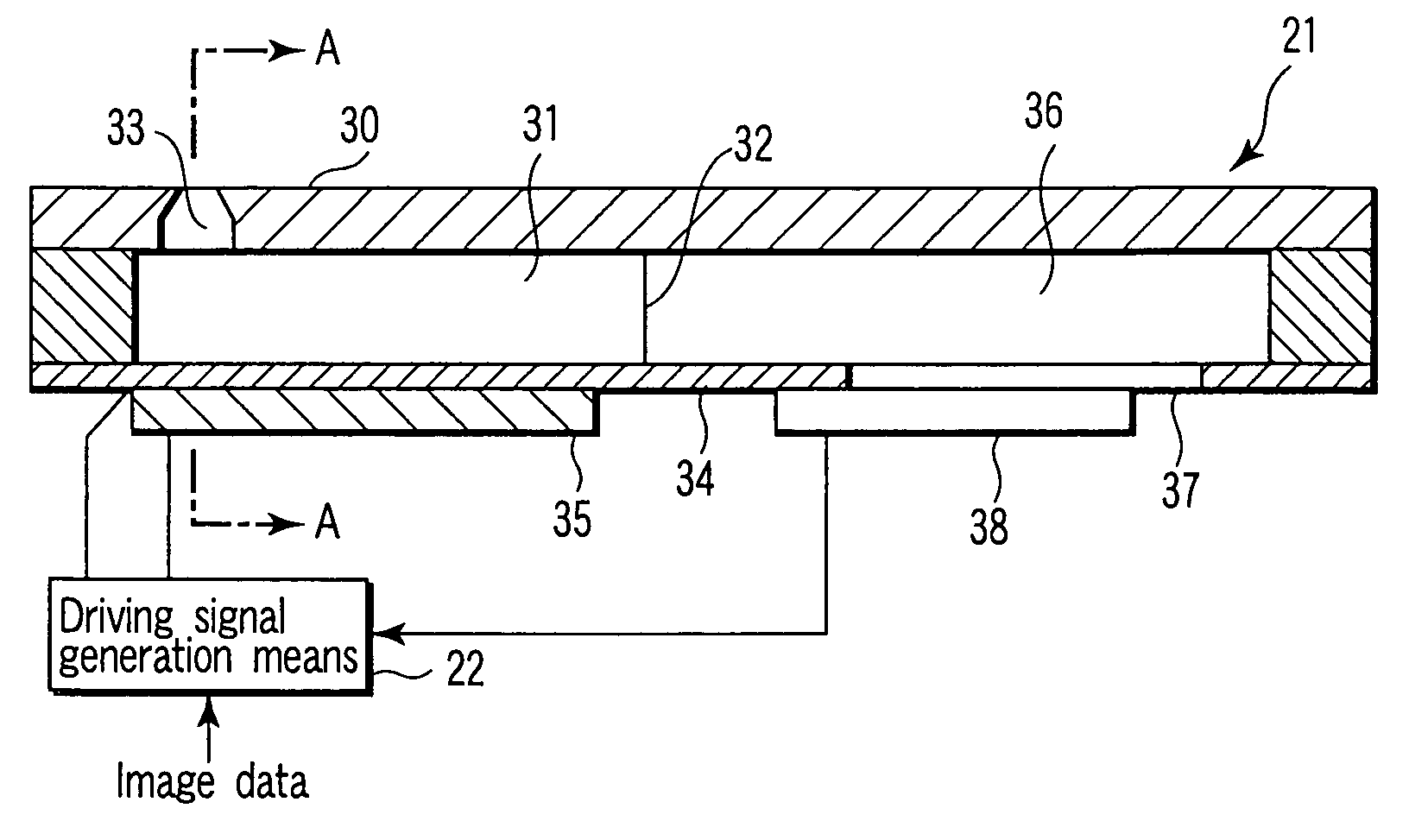
[0038]Embodiments of the present invention will now be described with reference to the accompanying drawings. FIG. 1 is a sectional view of the main part of an ink-jet recording head according to the present invention. FIG. 2 is a sectional view taken along line A—A of FIG. 1. Referring to FIGS. 1 and 2, an ink jet head 21 is divided into a plurality of pressure chambers 31 for containing ink. A partition wall 32 is formed between adjacent pressure chambers 31. Each of the pressure chambers 31 has a nozzle 33 for ejecting ink drops. The nozzle 33 is formed in a nozzle plate 30. A vibrating plate 34 is formed on the bottom of each of the pressure chambers 31. A piezoelectric member 35 is fixed on the underside of the vibrating plate 34. The vibrating plate 34 and piezoelectric member 35 make up an actuator.

[0039]The ink-jet head 21 includes a common pressure chamber 36 communicating with each of the pressure chambers 31. The common pressure chamber 36 is supplied with ink from ink su...

second embodiment

[0061]In order to resolve the above problem, an ink-jet recording apparatus according to the present invention will now be described with reference to FIG. 10. Referring to FIG. 10, a tube 42 is connected to a common ink chamber 36 through an ink supply inlet 37 and a filter 41. The tube 42 is provided with an ink filling pump 43 that allows ink to flow in forward and backward directions. The inlet of the pump 43 is connected to an ink bottle 44. A driving unit 45 controls the pump 43 to allow ink to flow forward and backward.

[0062]Assume that the ink-jet recording apparatus with the above configuration turns off and sits idle for a long period of time and ink in the nozzle 33 considerably increases in viscosity or solidifies. First, the pump 43 is driven in the backward direction to cause ink to flow from the nozzle 33 in the direction of arrow a through the tube 42. The ink is agitated in a pressure chamber 31. Then, the pump 43 is driven in the forward direction to discharge ink ...


PUM


Abstract

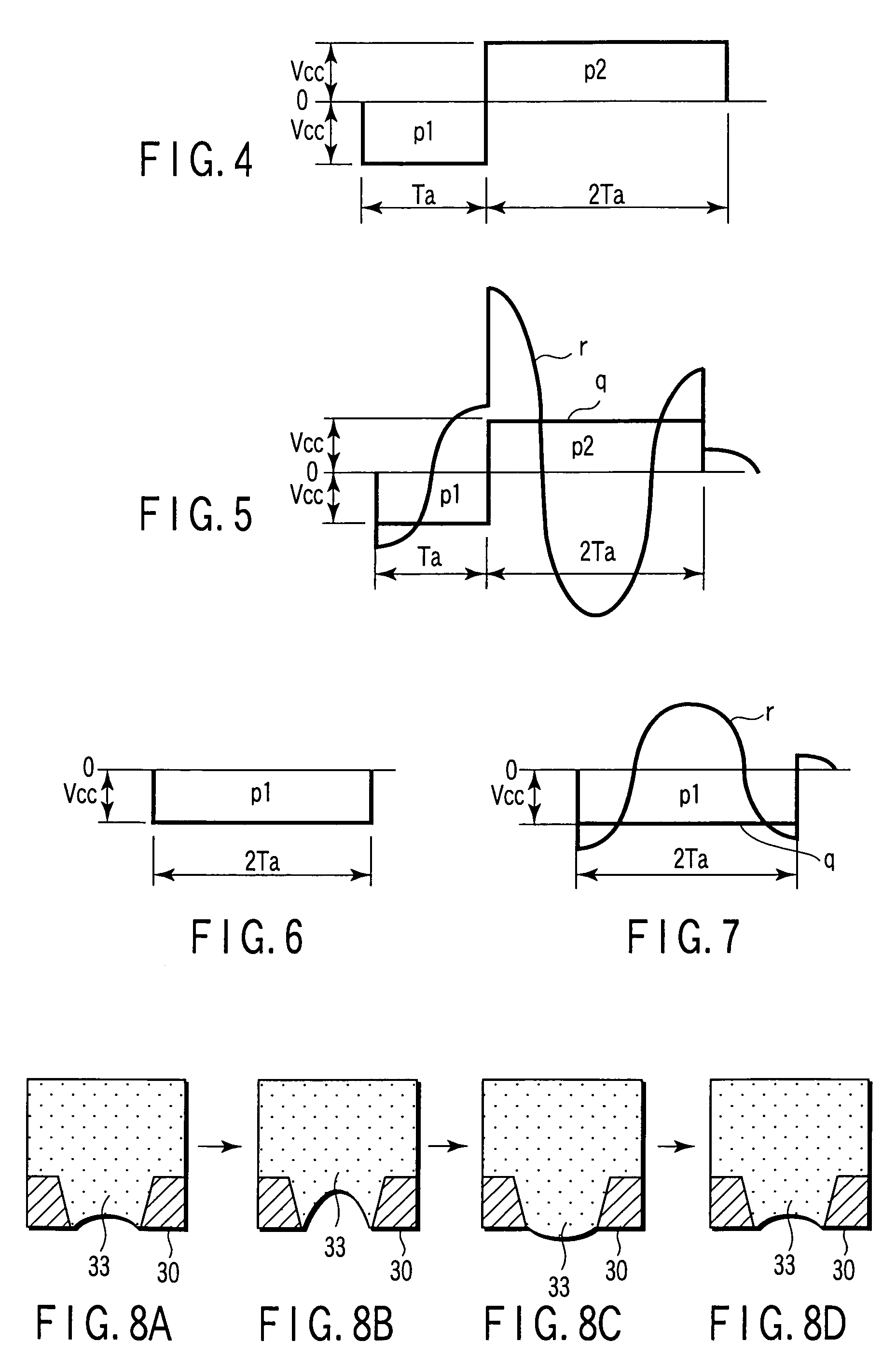
An ink-jet recording apparatus includes a pressure chamber that contains ink, a nozzle communicating with the pressure chamber, which ejects the ink from the pressure chamber, an ink-jet head having an actuator that increases and decreases the capacity of the pressure chamber, and a driving signal generation unit that supplies the actuator with a driving signal to eject an ink drop from the nozzle. When no ink is ejected from the nozzle, the actuator is supplied with a very low pressure driving signal to increase the capacity of the pressure chamber and then return the increased capacity to an original size. The pulse width of the very low pressure driving signal is about twice as long as a pressure propagation time period during which a pressure wave in the ink propagates through the pressure chamber.

Description

CROSS-REFERENCE TO RELATED APPLICATIONS[0001]This application is based upon and claims the benefit of priority from prior Japanese Patent Application No. 2003-201719, filed Jul. 25, 2003, the entire contents of which are incorporated herein by reference.BACKGROUND OF THE INVENTION[0002]1. Field of the Invention[0003]The present invention relates to an ink-jet head driving method and an ink-jet recording apparatus in which an ink drop is ejected from a nozzle by varying the capacity of a pressure chamber that contains ink.[0004]2. Description of the Related Art[0005]FIG. 11 illustrates a configuration of a conventional ink-jet recording head. In FIG. 11, reference numeral 1 indicates an ink-jet recording head. The ink-jet recording head 1 includes a plurality of pressure generating chambers 2 to be filled with ink, a nozzle plate 3 provided at one end of each of the pressure generating chambers 2, a nozzle 5 provided in each of the pressure generating chambers 2 to eject an ink drop ...

Claims


Application Information

Patent Timeline
Patent Type & Authority Patents(United States)
IPC IPC(8): B41J29/38B41J2/175B41J2/045B41J2/055
CPCB41J2/04518B41J2/0452B41J2/04541B41J2/04596B41J2/04581B41J2/04588B41J2/04563
Inventor NORIGOE, TAKASHI
Owner TOSHIBA TEC KK
Learn More