
Fast method for adjusting downlink transmitted power

a transmission power and transmission line technology, applied in power management, electrical equipment, radio transmission, etc., can solve the problems of increasing the transmission power of node b unnecessarily, affecting reducing the transmission speed of node b, so as to increase the transmission capacity and reduce the spread of transmission power

Inactive Publication Date: 2006-12-26
WSOU INVESTMENTS LLC +1
View PDF3 Cites 4 Cited by
  • Summary
  • Abstract
  • Description
  • Claims
  • Application Information

AI Technical Summary

Benefits of technology

[0012]The present invention is directed to an algorithm for calculating a correction value to be applied to a given slot in an adjustment period for power correction. A predetermined total amount of power adjustment to be applied over the adjustment period is divided to determine an individual correction value that can be applied to single slots in the adjustment period. The correction value is then distributed over the adjustment period as fast as possible so that the transmitted power in a given active set converges quickly toward the total power adjustment amount, diminishing the spread of transmitted power among members in the active set and thereby increasing the downlink capacity.

Problems solved by technology

Due to errors in the uplink control channel radio links, however, the TPC commands received by each Node B may be different; for example, during soft handover, stronger radio links will have a lower probability of TPC bit errors than weaker radio links.
If the radio link is extremely weak, the TPC bits received by the Node B will be random, breaking the inner-loop power control and potentially increasing the transmitted power of the weak link unnecessarily.
Because the inner loop at each Node B responds to the TPC commands it receives, cumulative TPC bit errors will cause the Node B transmitted power to drift substantially if the transmitted power levels of each Node B in the active set are left unsynchronized.
If the transmitted power levels are not kept synchronized, the relative power spread between radio links increases, reducing downlink system capacity and increasing the probability of dropped signals during handover.

Method used


Image

  • Fast method for adjusting downlink transmitted power
  • Fast method for adjusting downlink transmitted power
  • Fast method for adjusting downlink transmitted power

Examples


Embodiment Construction

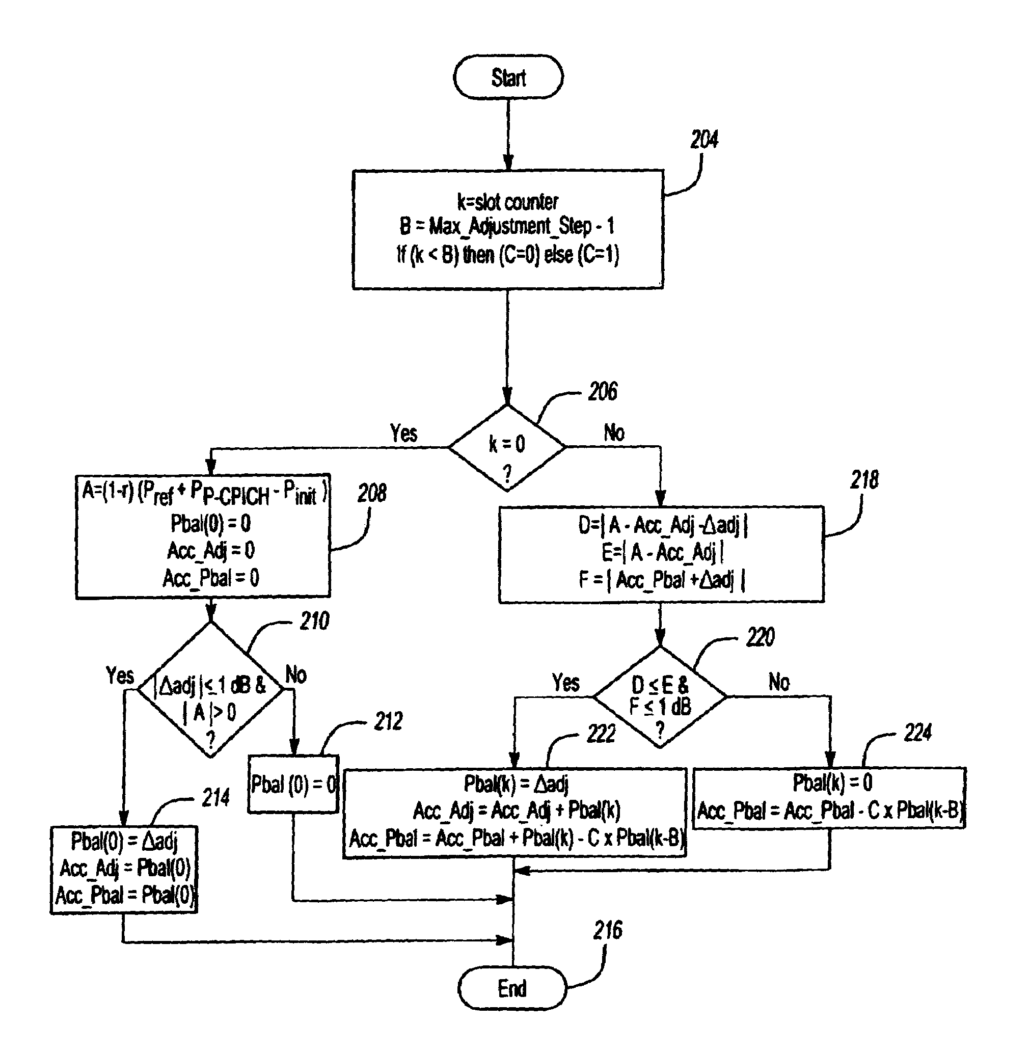
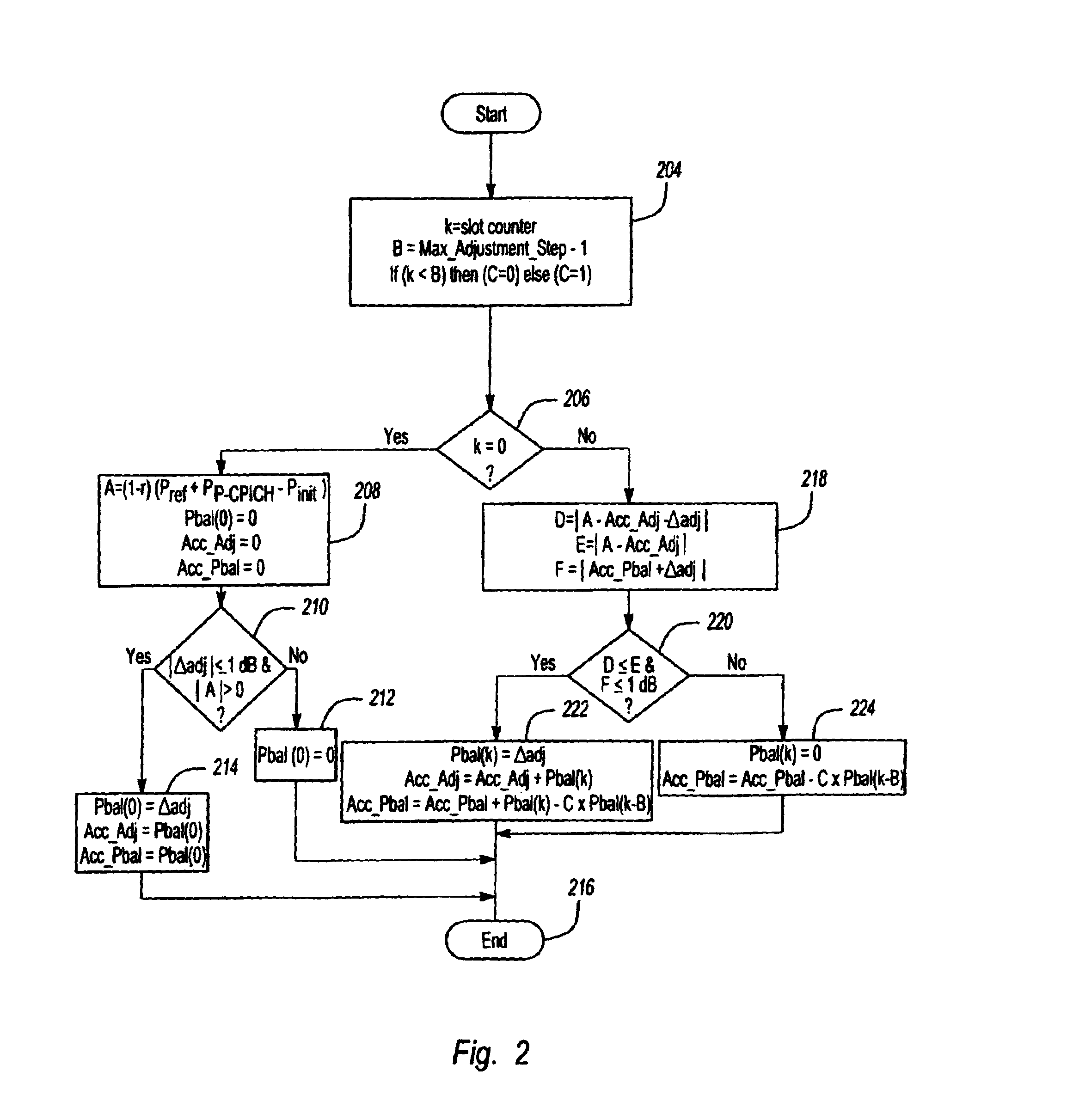
[0016]FIG. 2 is a flow diagram illustrating an algorithm for adjusting the downlink transmitted power to equalize the values at each Node B in an active set. For purposes of illustration only, the example described below focuses on power adjustment according to parameters defined by the UMTS standard, but the inventive algorithm can be applied to any wireless system using any standard. Parameters and formulas defined by the UMTS standard and referenced in this description are defined below in Table 1.

[0017]

TABLE 1UMTS Parameter Name or FormulaDefinition of Parameter∑k=Adjustment_Period⁢Pbal⁡(k)=(1-r)⁢(Pref+PP-CPICH-Pinit)aggregate amount of power adjustmentcorrection to be superimposed on the innerloop power control adjustmentsPbal(k)amount of power correction applied in slot kAdjustment_Periodperiod in which a power adjustmentcorrection ΣPbal(k) is applied (range 1 to256 frames)radjustment ratio defining the convergencerate used in the adjustment periodPrefdownlink reference power ...


PUM


Abstract

An algorithm calculates a correction value to be applied to a slot in an adjustment period for power correction. For each slot, the algorithm determines whether adding a correction value in a given slot would bring the actual accumulative adjustment value closer or farther from a total desired power correction value for the adjustment period. In one embodiment, the correction value is added to consecutive slots in the adjustment period to conduct the correction as fast as possible. The algorithm also checks the total amount of adjustment applied to the slots over a sliding adjustment window within the adjustment period to make sure that the total amount of adjustment applied to the slots in the adjustment window do not exceed a predetermined maximum threshold.

Description

BACKGROUND OF THE INVENTION[0001]1. Field of the Invention[0002]The present invention relates to wireless communication systems.[0003]2. Description of the Related Art[0004]Communication systems, such as wireless systems, are designed to meet various demands of subscribers. Service providers continuously seek ways to improve the overall performance of the communication system. As wireless communications become more and more popular for subscribers to obtain data (i.e., email or information from the internet), communication systems must be capable of a higher throughput.[0005]There are two directions of data flow in such systems. Communications from a base station to a mobile device are considered to flow in a downlink direction while the communications originating at the mobile device are considered to flow in an uplink direction. Most of the work in this area has focused on the downlink flow of information, which is to the mobile devices (typically from a base station, called “Node...

Claims


Application Information

Patent Timeline
Patent Type & Authority Patents(United States)
IPC IPC(8): H04Q7/20H04B7/00H04B7/005H04W52/08
CPCH04W52/08
Inventor CHEN, XIAOHUANABHANE, WALID E.SALVARANI, ALEXANDRO
Owner WSOU INVESTMENTS LLC
Learn More