
Using active circuits to compensate for resistance variations in embedded poly resistors

a poly-resistor and active circuit technology, applied in the field of semiconductor integrated circuits, can solve the problem that the type of variation is not acceptable in many applications that require precision resistors

Active Publication Date: 2006-12-26
STMICROELECTRONICS SRL
View PDF6 Cites 3 Cited by
  • Summary
  • Abstract
  • Description
  • Claims
  • Application Information

AI Technical Summary

Problems solved by technology

This type of variation is not acceptable for many applications that require precision resistors, for example, the termination resistors used in LVDS and PECL applications.

Method used


Image

  • Using active circuits to compensate for resistance variations in embedded poly resistors
  • Using active circuits to compensate for resistance variations in embedded poly resistors
  • Using active circuits to compensate for resistance variations in embedded poly resistors

Examples


Embodiment Construction

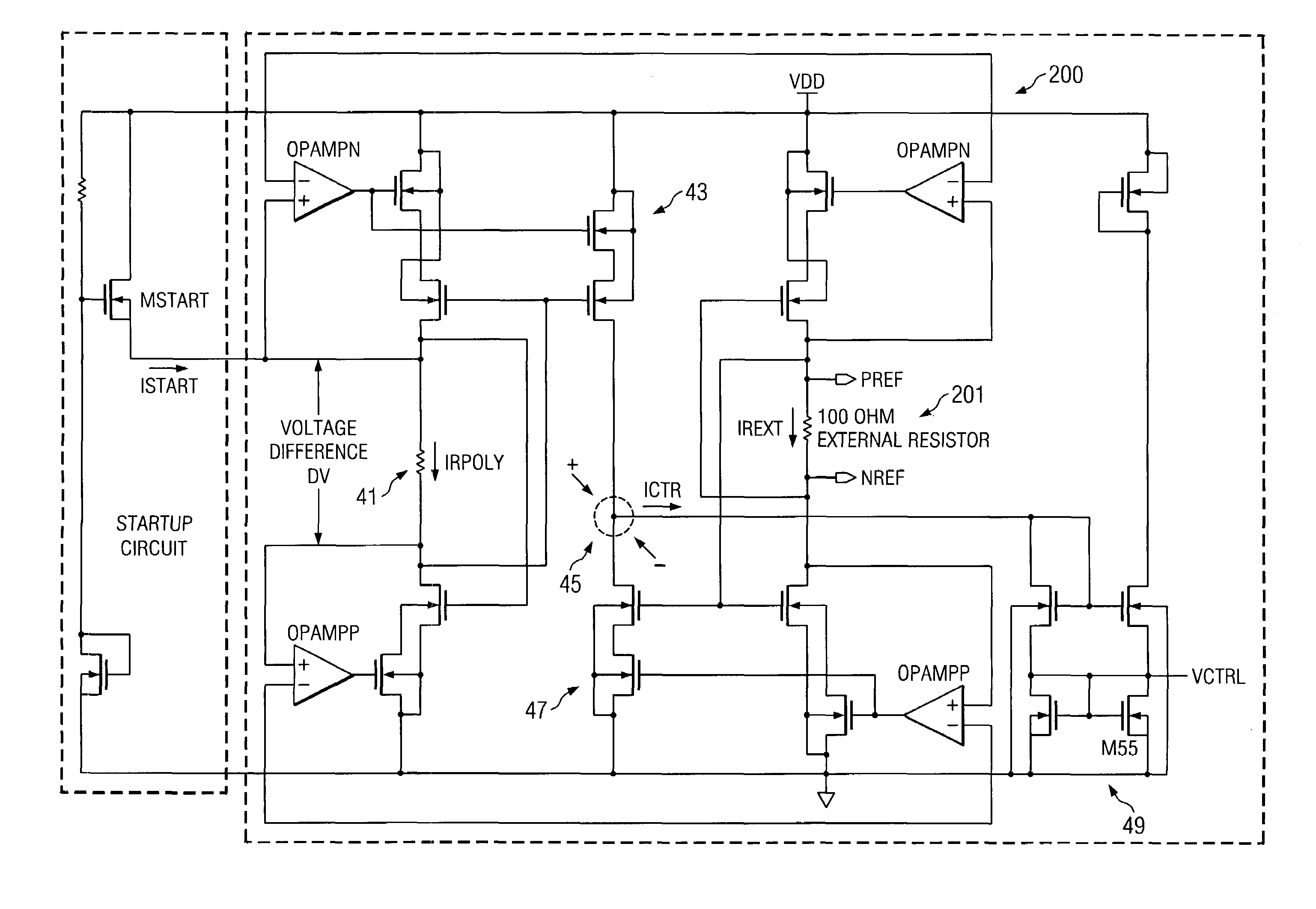
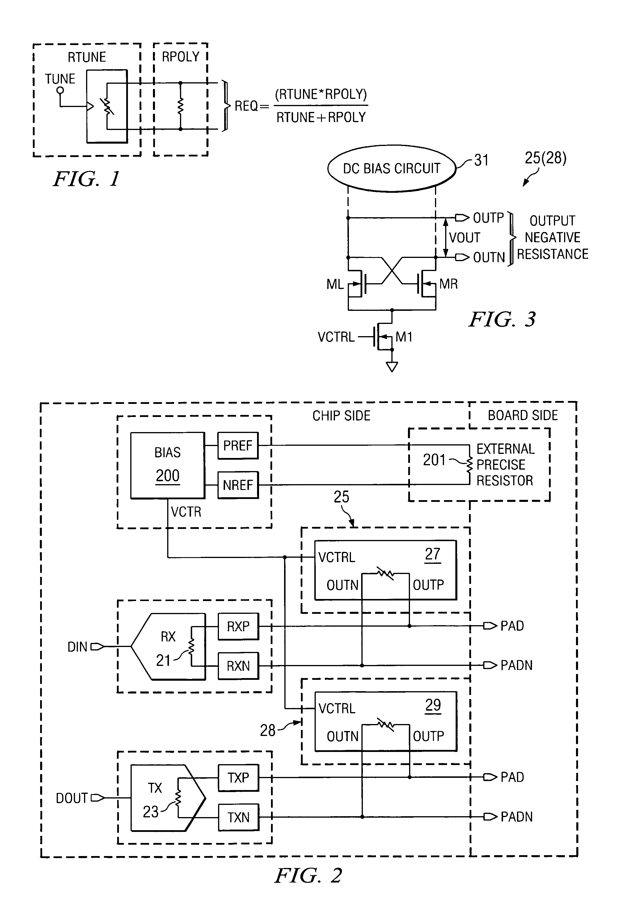
[0009]FIG. 1 illustrates a general approach to compensate for variations in the resistance of an unsalicided poly resistor, such as produced by a conventional CMOS process. The poly resistor (Rpoly) of FIG. 1 can exhibit an actual resistance that varies + / −30% or more from the nominal value of the poly resistor, for example because of PVT (process, voltage, temperature) variations. This situation is well known in the art. According to the invention, a tunable compensating resistance (Rtune) is provided in parallel with the target poly resistor (Rpoly) which results in a tunable equivalent resistance (Req) defined as shown in FIG. 1. More specifically, the equivalent resistance is given by

[0010]Req=Rtune×RpolyRtune+Rpoly(1)

If the maximum variation of the poly resistor Rpoly is known, then the Rpoly can be sized, in the typical PVT conditions, lower than the desired resistance Req, so that:

[0011]Rpoly=Req-(dRpolyRpoly)⁢❘max⁢×Rpoly(2)

[0012]Because Rpoly is less than Req, the value of t...


PUM


Abstract

Variations in the actual resistance of a target poly resistor in a semiconductor integrated circuit can be compensated for by using an active circuit that provides a negative resistance in parallel with the target resistor. This produces a tuned resistance that is closer to a desired resistance than is the actual resistance of the target resistor.

Description

TECHNICAL FIELD OF THE INVENTION[0001]The invention relates generally to semiconductor integrated circuits and, more particularly, to resistors in semiconductor integrated circuits.BACKGROUND OF THE INVENTION[0002]The unsalicided poly resistor structures provided by conventional semiconductor integrated circuit technology, such as CMOS technology, typically provide an actual resistance value that can vary + / −30% or more from the nominal resistance value of the poly resistor structure. This type of variation is not acceptable for many applications that require precision resistors, for example, the termination resistors used in LVDS and PECL applications.[0003]In some conventional techniques, the resistance variation is compensated for by providing additional poly resistors which can be switched into or out of either series or parallel combination with a target resistor, in order to compensate for the aforementioned variation of the target resistor. In such approaches, the resistance ...

Claims


Application Information

Patent Timeline
Patent Type & Authority Patents(United States)
IPC IPC(8): H03L5/00
CPCH03F1/56H03H11/52
Inventor LA ROSA, ROBERTO
Owner STMICROELECTRONICS SRL
Learn More