


Quick Research
Generate reliable direction feasibility study reports for your R&D in just a few steps.

Technical Q&A
Discover and master advanced knowledge NOW. Basics, ideas, possibilities, all at once.

Find Solutions
As an expert in R&D theories, this can generate solutions to your technical problems instantly.

Evaluate Feasibility
Analyze your overall solution with one click, know your potential R&D risks in advance.

Monitor Landscape
Get weekly tech updates, stay abreast of the latest tech innovations and key insights.
Artificial pond
a technology of artificial ponds and ponds, applied in water cleaning, lighting and heating apparatus, separation processes, etc., can solve the problems of more maintenance, less efficiency of dc motors, and more expensive dc motors, and achieve the effect of reducing shock hazards
- Summary
- Abstract
- Description
- Claims
- Application Information
AI Technical Summary
Benefits of technology
Problems solved by technology
Method used
Image

Examples
Embodiment Construction
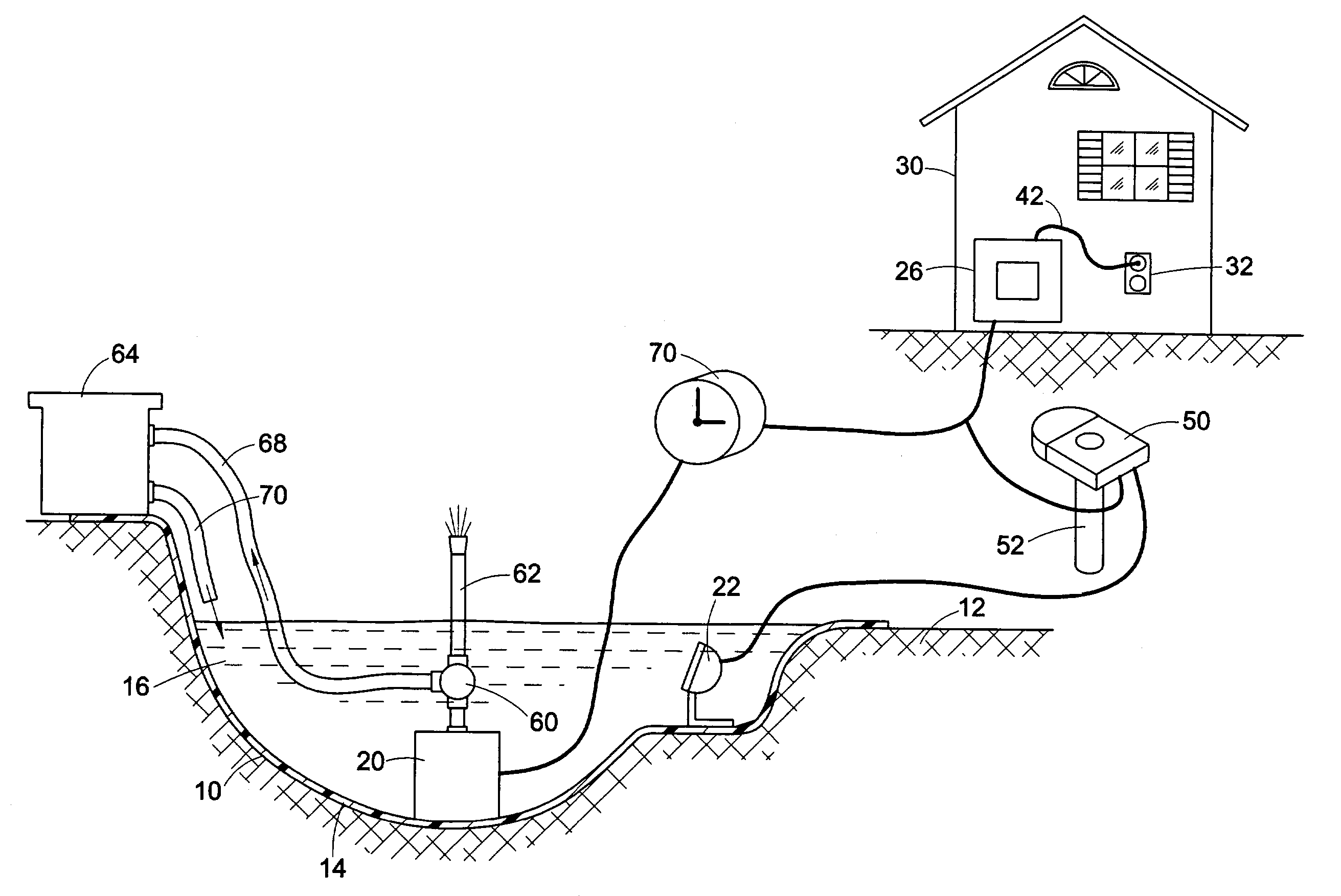
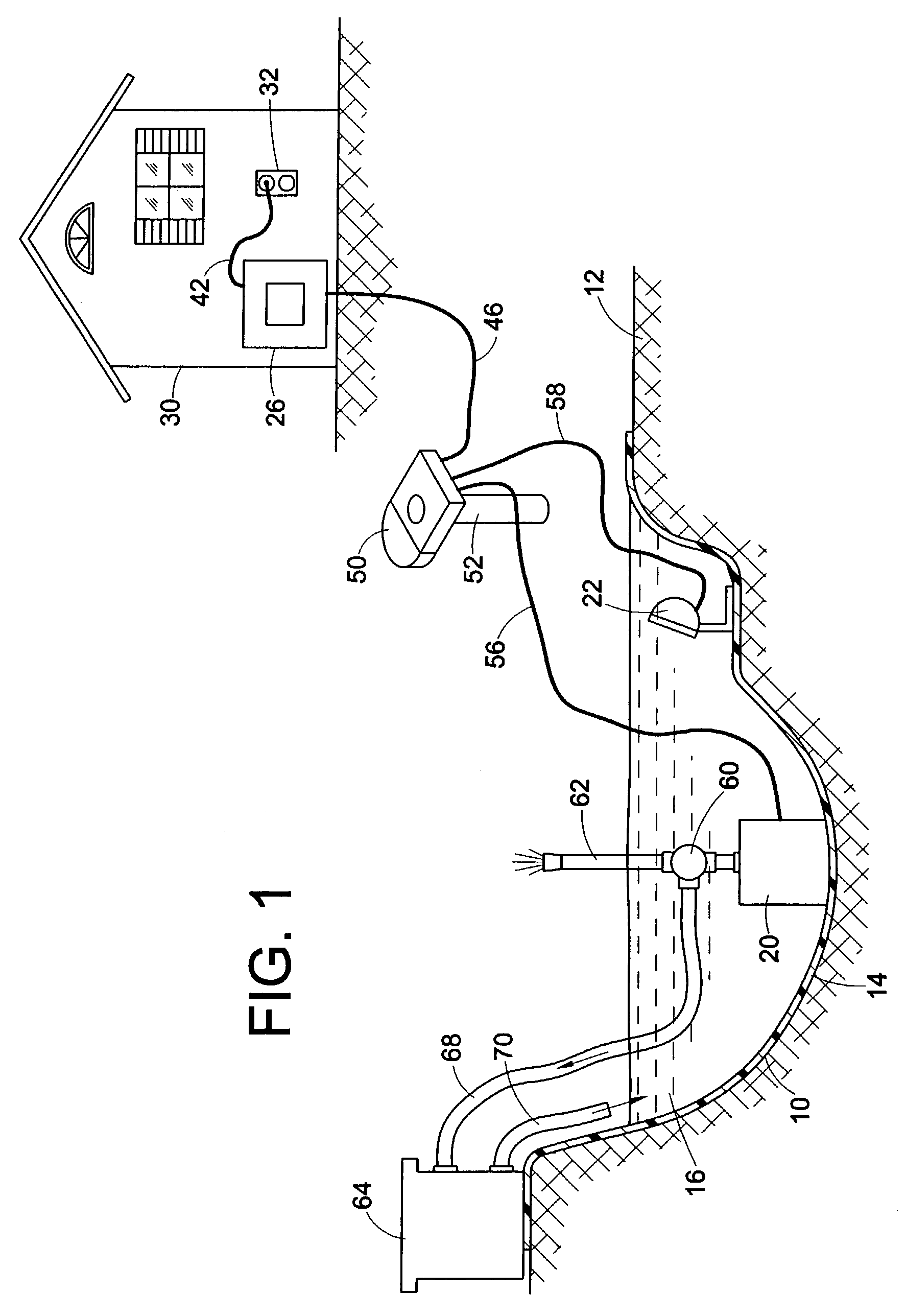
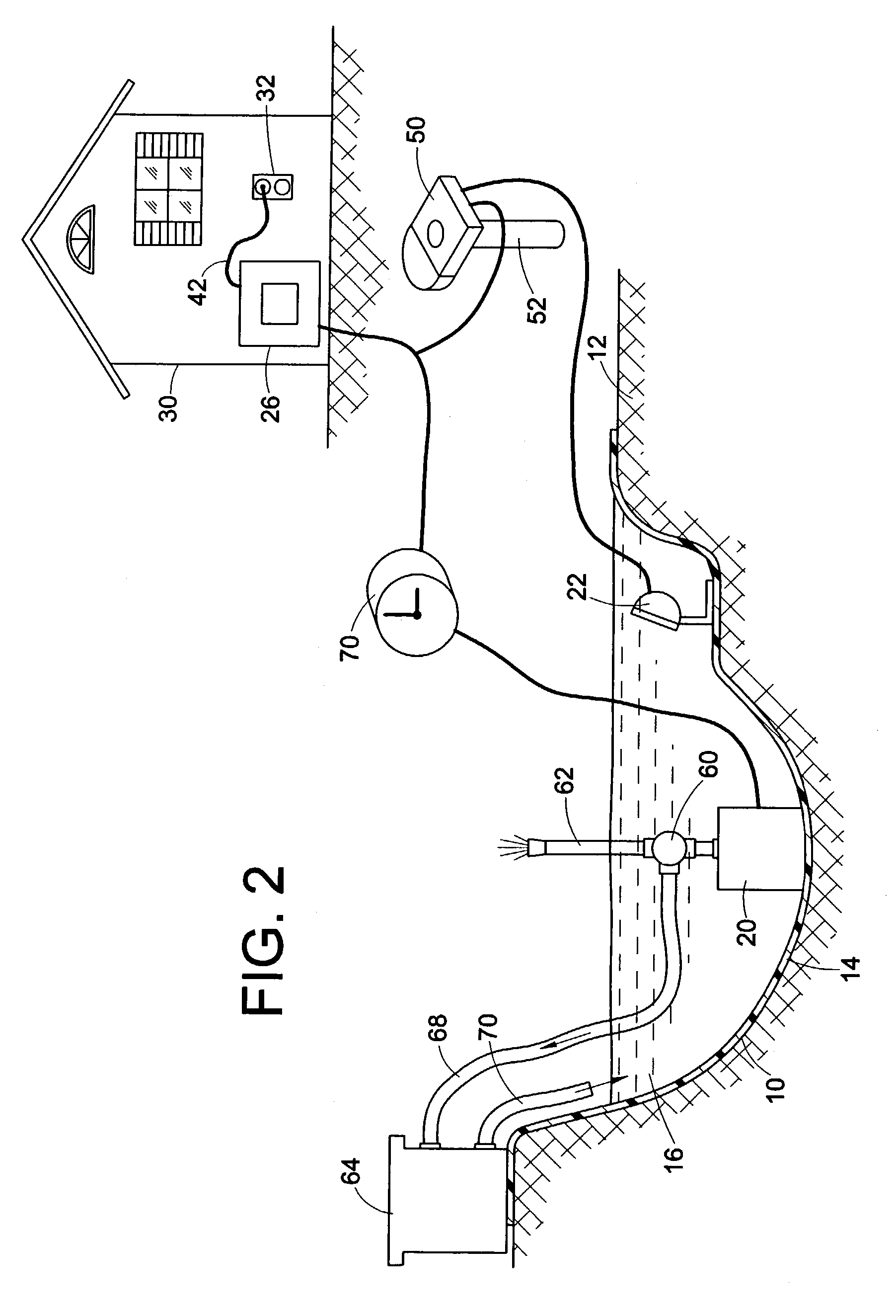
[0015]Referring now to the drawing, wherein the showings are for purposes of illustrating a preferred embodiment of the invention only and not for purposes of limiting same, FIG. 1 shows the components of an artificial pond. A depression 10 in the earth 12 is lined with an impervious liner 14 for holding water 16.
[0016]A submersible motor pump unit 20 and a submersible lamp 22 are positioned on liner 14 beneath the surface of water 16. A step down transformer 26 is attached to the outside surface of a wall on a building 30 that has a conventional 120 volt AC outlet 32. Transformer 26 has a plug and wire 42 that connects transformer 26 with the 120 volt AC power supply at electrical outlet 32.
[0017]Step down transformer 26 converts 120 volts AC to a low level AC voltage that is not greater than 15 volts AC and preferably about 12 volts AC. A low voltage output power wire 46 attached to transformer 26 and forming an integral part thereof is at least forty feet long, and more preferabl...
PUM
| Property | Measurement | Unit |
|---|---|---|
| Length | aaaaa | aaaaa |
| Length | aaaaa | aaaaa |
| Electric potential / voltage | aaaaa | aaaaa |
Abstract
Description
Claims
Application Information
 - R&D Engineer
- R&D Manager
- IP Professional
- Industry Leading Data Capabilities
- Powerful AI technology
- Patent DNA Extraction
Browse by: Latest US Patents, China's latest patents, Technical Efficacy Thesaurus, Application Domain, Technology Topic, Popular Technical Reports.
© 2024 PatSnap. All rights reserved.Legal|Privacy policy|Modern Slavery Act Transparency Statement|Sitemap|About US| Contact US: help@patsnap.com