
Tape dispenser

a dispenser and tape technology, applied in the field of tape dispensers, can solve the problems of inability to maintain the tape edge straight, the tape is not only time-consuming and cumbersome, and the tape is not easy to maintain, so as to achieve the effect of convenient supply of a tape roll and manipulation

Inactive Publication Date: 2006-12-26
HENKEL CORP
View PDF32 Cites 9 Cited by
  • Summary
  • Abstract
  • Description
  • Claims
  • Application Information

AI Technical Summary

Benefits of technology

[0007]In accordance with the present invention, a tape dispenser is provided by which the foregoing and other problems and disadvantages encountered in connection with the application of tape along adjacent surfaces, either manually or through the use of a dispenser having tape applicating capability, are minimized or overcome. More particularly, a tape dispenser in accordance with the present invention enables tape to be applied along adjacent surfaces with accuracy of the linear positioning of an edge of the tape along the adjacent surfaces so as to avoid uncovered spaces on the underlying surface which are intended to be covered. This is achieved in part by controlling the contour of the tape as it is dispensed and applied onto the underlying surface, by stabilizing the tape applicating procedure through the use of an applicator portion of the dispenser in place of a user's fingers, and by enabling the tape to be pulled from the dispenser with a uniform pulling force applied thereto. More particularly, with regard to the tape contour, the dispenser includes a tape guide which serves to bow or arch the tape transverse to the direction of application thereof and as the tape exits the applicating end of the dispenser with the arcuate contour of the tape being concave in the direction from the dispenser toward the underlying surface. This contour rigidifies the tape against flexure or bending transverse to the direction of application much like that of an arched metal tape measure. With respect to so rigidifying, the tape contour could be convex as well as concave. Further, the arched contour provides for the edges of the tape to spread laterally outwardly as the tape is applied to the underlying surface, thus assuring the edge of the tape along the adjacent surfaces being positioned as desired with respect thereto. Accordingly, tape can be laid along a path between adjacent surfaces without having to repeatedly lift and reposition the tape during the application thereof. Moreover, even if lifting of the tape becomes necessary, the contour of the tape, the stability of the dispenser and its manipulation by the user enable the lifting and re-application to be more quickly and more accurately achieved than heretofore possible.
[0008]In accordance with a further aspect of the invention, the applicator is a molded, one-piece plastic component and the tape applicator at the exit end of the dispenser is provided with an integral serrated cutting edge which promotes the ability to apply the tape fully into a corner between right angled edges and to accurately cut the tape when it is fully into the corner. This capability avoids the need to repeatedly pull the tape away from the corner, cut and then reposition the tape with the hope that the tape has been cut to the appropriate length to fill the corner. In this respect, at the very least, the serrated cutting edge perforates the tape to provide an indication of the line along which the tape needs to be tom or cut in order to fill the corner.
[0009]In accordance with another aspect of the invention, the dispenser includes a tape roll supporting arrangement which enables a user to grasp and tightly support the dispenser without interfering with free rotation of the tape roll during a tape dispensing and applicating procedure.

Problems solved by technology

This process is not only time consuming and cumbersome in that it most often requires the withdrawal and re-application of the tape to the underlying surface in an effort to control the position of the tape edge along the adjacent surfaces.
Moreover, this process makes it extremely difficult if not possible to maintain the tape edge straight and to avoid the occurrence of gaps between the tape edge and the adjacent surface.
Such difficulties result from the instability of application caused by the user's one hand holding the tape roll and the other hand attempting to press the dispensed tape into place and the application of a varying pulling force on the tape roll during the tape applying procedure which is caused by the tape roll being handheld and thus grasped with different holding forces by the user during the application process.
Another problem encountered in connection with the taping of adjacent, angularly, related surfaces is encountered in cutting the tape at a corner between right angle surfaces such as window frame members.
Attempting to tear the tape and position it in a corner is nearly impossible, and a good sharp corner requires cutting the tape at or a little short of the corner at one end and then beginning the adjacent right angle run by overlapping the previously cut end.
This process is time consuming and, with regard to the first cut, usually requires pulling a portion of the tape away from the underlying surface in order to access the tape for cutting.
In pulling the tape up from the underlying surface, it is extremely difficult to control a handheld tape roll or a tape roll on a dispenser so as to avoid further dispensing of tape from the roll and the consequent extra length of tape which has to be withdrawn again and cut in an effort to conform with the corner edges.

Method used


Image

  • Tape dispenser
  • Tape dispenser
  • Tape dispenser

Examples


Embodiment Construction

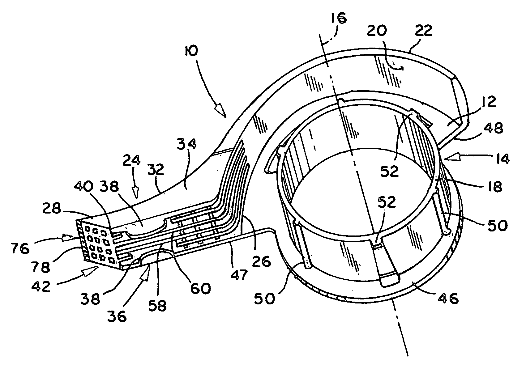
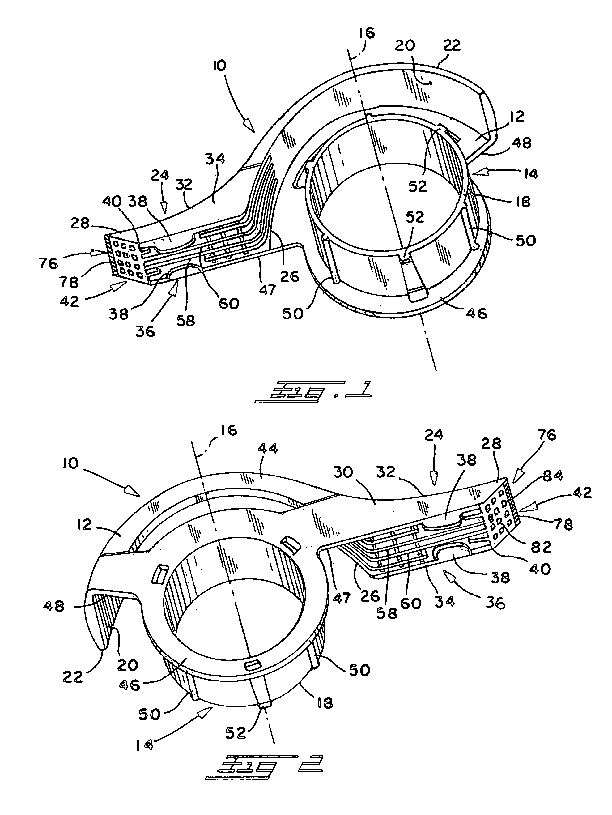
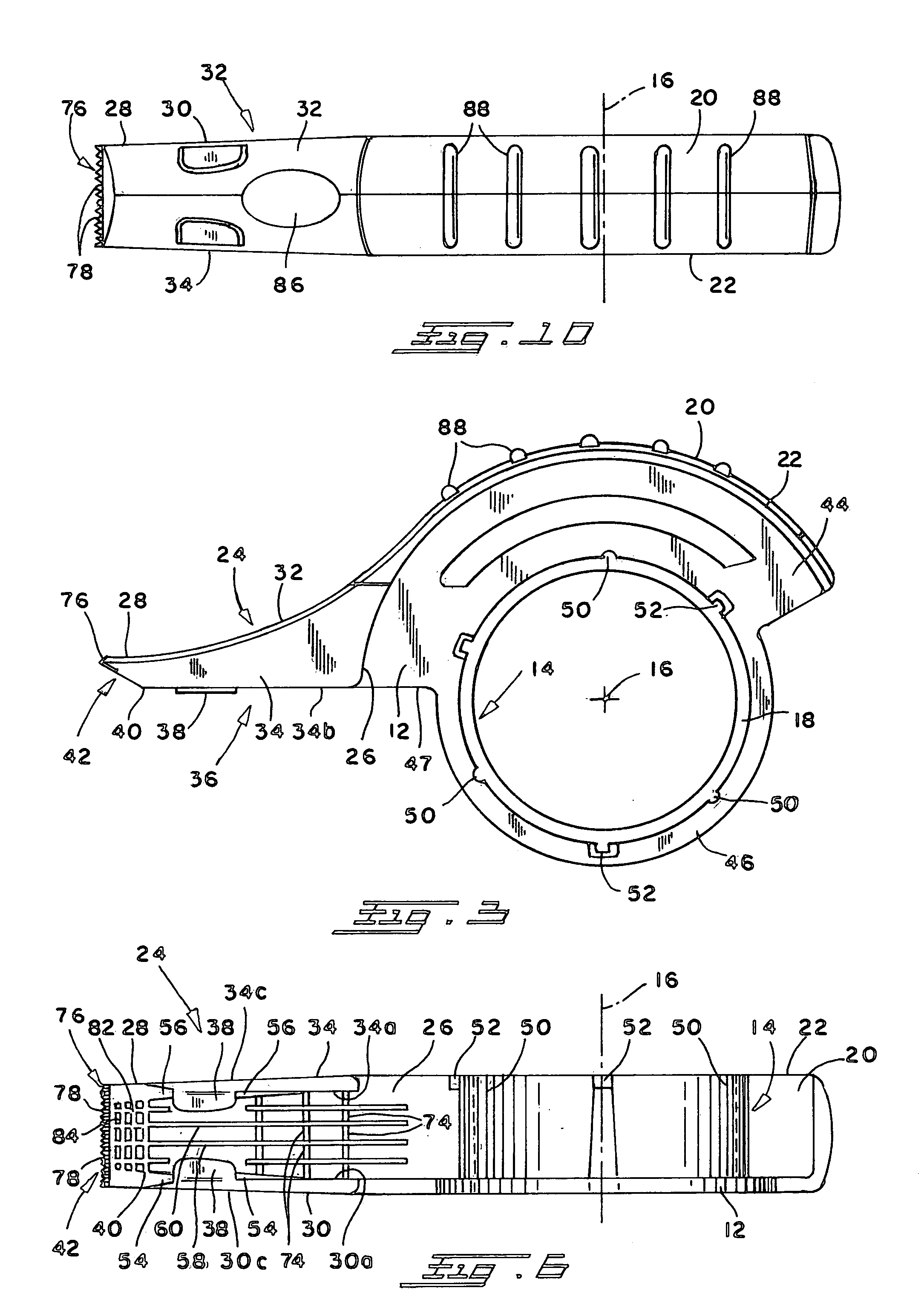
[0032]Referring now in greater detail to the drawings wherein the showings are for the purpose of illustrating preferred embodiments of the invention and not for the purpose of limiting the invention, a tape dispenser and applicator 10 in accordance with the present invention is produced from a suitable plastic material and includes a planar wall 12, a tape roll support in the form of an annular hub 14 extending transverse to wall 12 and having an axis 16 and an axially outer end 18 spaced from wall 12 a distance slightly greater than the width of a roll of tape to be mounted thereon. The dispenser further includes an arcuate wall 20 radially spaced from hub 14 a distance generally corresponding to and at least slightly greater than the radial thickness of a roll of tape to be mounted on the latter. Wall 20 extends transverse to planar wall 12 and has an axially outer end 22 generally axially coextensive with outer end 18 of hub 14. The dispenser further includes a dispensing arm 24...


PUM

PropertyMeasurementUnit
restraining rotationaaaaaaaaaa
timeaaaaaaaaaa
holding forcesaaaaaaaaaa

Abstract

A tape dispenser comprises a cylindrical hub for rotatably supporting a roll of tape, and a dispensing arm extends radially outwardly of the hub and has a tape guide on the bottom thereof by which tape is arched concavely toward an underlying surface as the tape is displaced from the dispenser and applied to the underlying surface. A brake arrangement on the dispenser is operable manually by a user to stop or otherwise control rotation of a tape roll during a dispensing operation.

Description

[0001]This application claims priority under 35 U.S.C. §119(e) and the benefit of provisional patent application Ser. No. 60 / 395,779, filed Jul. 15, 2002 entitled TAPE DISPENSER which is incorporated herein by reference.BACKGROUND OF THE INVENTION[0002]This invention relates to the art of tape dispensers and, more particularly, to an improved tape dispenser which can be manipulated to apply a tape along a path with improved control of the dispensing and the location of an edge of the tape relative to the path.[0003]The present invention finds particular utility in connection with the dispensing of masking tape and the application of such tape along the juncture between angularly related surfaces such as a window pane and a frame or mullion to be painted and, accordingly, will be disclosed and described herein in detail in connection with such use. At the same time, however, it will be appreciated that the dispenser can be used with tapes other than masking tape and in connection wit...

Claims


Application Information

Patent Timeline
Patent Type & Authority Patents(United States)
IPC IPC(8): B32B37/22B65H35/00
CPCB65H35/0033B65H2402/412Y10T156/1795Y10T156/1348Y10T156/18Y10T156/1365Y10T156/1788Y10T225/269Y10T225/294
Inventor VAN TYLE, PETER R.FERGOT, DAVID L.MARTINEZ, JOSE M.
Owner HENKEL CORP
Learn More