
Freestanding penholder

a penholder and freestanding technology, applied in the field of stand, can solve the problems of limited use range of the device, difficult to find, limit the usefulness of the penholder, etc., and achieve the effect of convenient location and us

Inactive Publication Date: 2006-12-19
MINEHART JOHN JOSEPH
View PDF17 Cites 14 Cited by
  • Summary
  • Abstract
  • Description
  • Claims
  • Application Information

AI Technical Summary

Benefits of technology

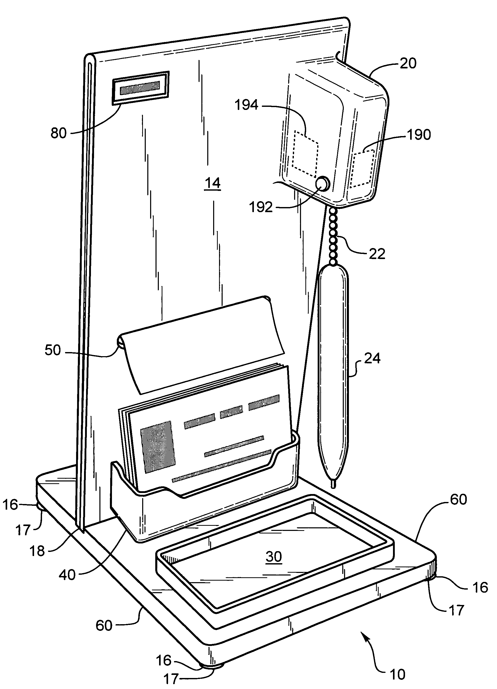
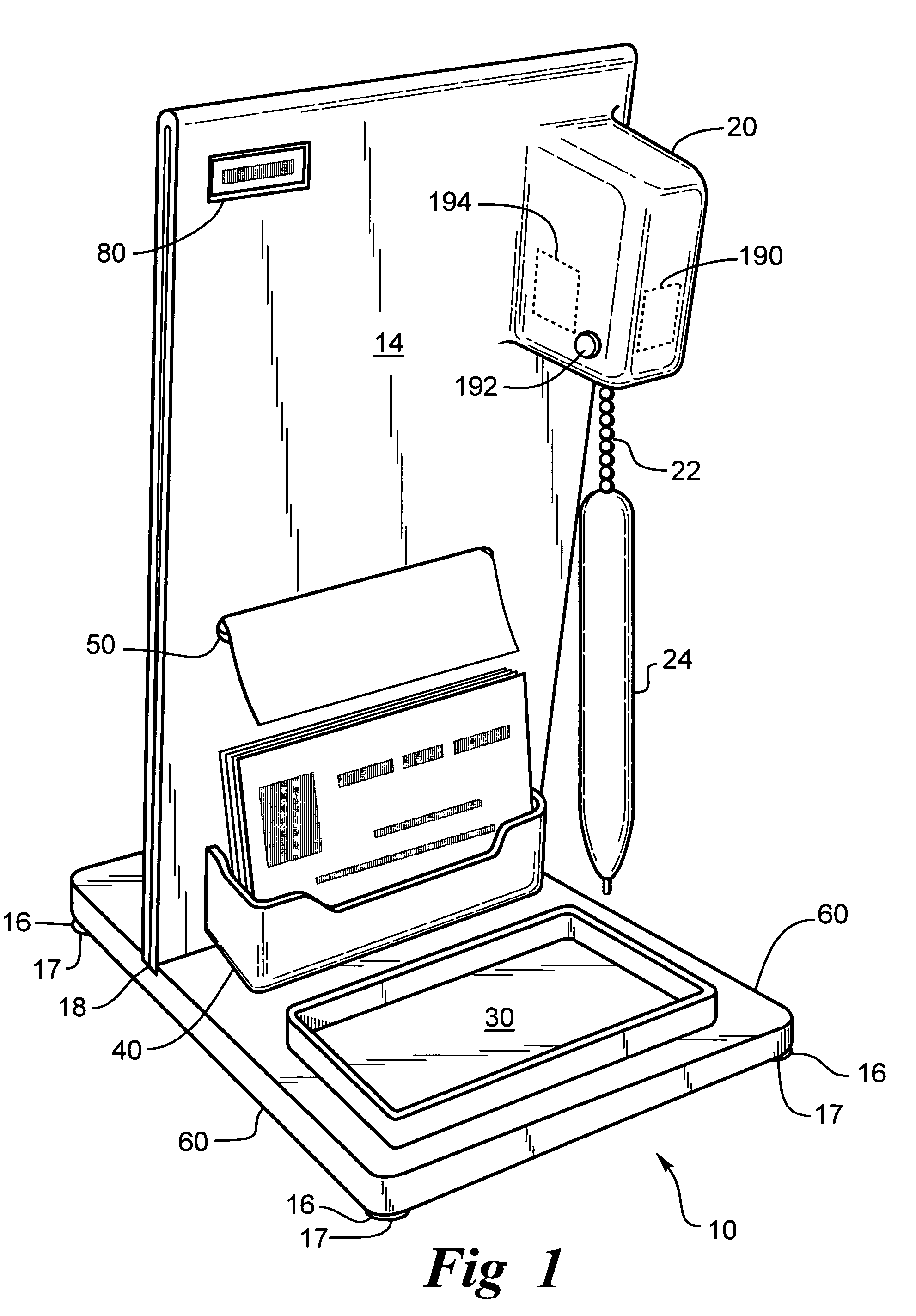
[0010]The freestanding penholder is useful for providing and retaining pens at a convenient location. The freestanding penholder comprises a base for setting the freestanding penholder on a tabletop, desktop or countertop or other surface. The base is weighted to help keep it from tipping over or sliding on the tabletop, desktop or countertop or other surface when the pen is in use. The base has an upstanding portion, which may be a panel or a tube for supporting the tether such that the pen will be suspended above the base when the tether is in a retracted position. The tether has a spring loaded retractor device for letting the tether unwind when it is in use and for rewinding the tether when the tether is not is use, thus suspending the pen in the air above the stand so that it can be easily located and used. The tether retractor can be located on the base or on the upstanding panel.
[0017]It is an object of the invention to provide a pen hanging from a tether on a pen stand for easy access to a pen.

Problems solved by technology

If the tether or the penholder is fixed to the tabletop, desktop or countertop it is not portable and limits the range of use of the device.
This limits the usefulness of the penholder.
Further for the penholder with a tether the pen can be placed in any number of places relative to the penholder and may not be easy to find on a desk covered with papers or other objects.

Method used


Image

  • Freestanding penholder
  • Freestanding penholder
  • Freestanding penholder

Examples


Embodiment Construction

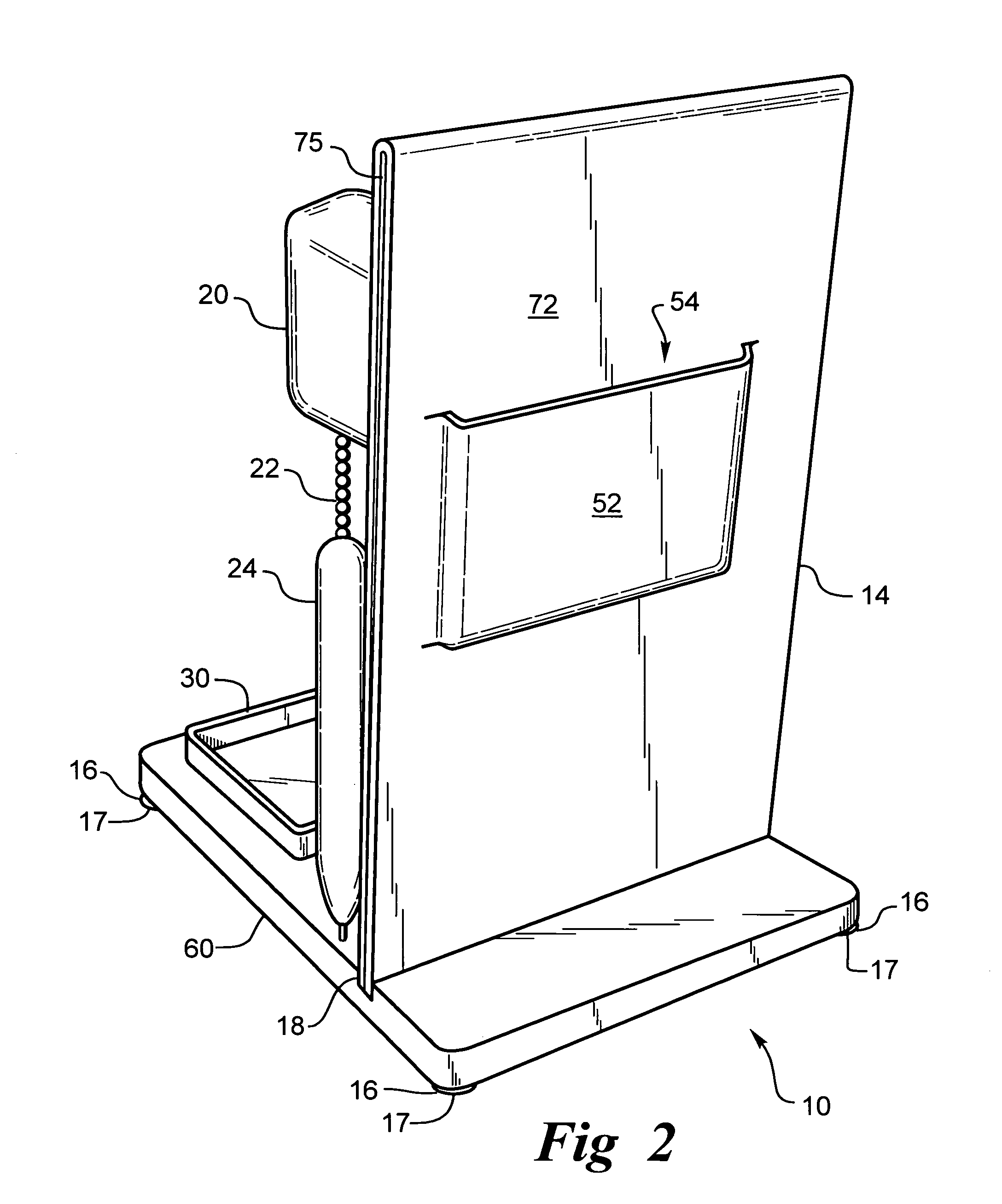
[0041]The freestanding penholder 10 has a base 12 optionally with feet 16 thereon for engaging a tabletop, desktop or countertop. The feet 16 may have non-skid pads 17 thereon to prevent the freestanding penholder from sliding around while in use. The base may be made of a clear acrylic or any material and be either clear or opaque. The base should have sufficient weight to remain in place while in use without sliding on a desktop, countertop, tabletop or other surface. The base 12 may have a slot 18 for inserting an upstanding wall 14 therein to hold the upstanding wall 14 in place relative to the base 12. The base 12 and the wall 14 may be separate pieces attached to each other or the freestanding penholder can be one integral piece having a base portion 12 and an upstanding wall portion 14.

[0042]In the first embodiment as shown in FIGS. 1 and 2 a retractable tether mechanism 20 is attached to the upstanding wall portion 14. The retractable tether mechanism 20 has a spring mechani...


PUM


Abstract

A penholder having a retractable tether for holding a pen in an upright position adjacent a vertical portion of the stand extending the when not in use for easily finding the pen. The tether extends when the pen is in use but does not interfere with use since little or no tension is exerted on the tether when it is extended. The tether prevents the pen from being taken away from the stand so that it is always available for use. The penholder can have paper holders, paper dispensers, advertising, a business card holder, or pamphlet holder attached, and may have an LCD for a clock, thermometer or calendar display. The penholder may also have a light attached. The base of the penholder may be weighted to help station the penholder on a desktop. The penholder can support trophies or awards and can be used as a promotional item.

Description

CROSS REFERENCE TO OTHER APPLICATIONS[0001]This invention relates to provisional application Ser. No. 60 / 511,371 filed Oct. 15, 2003.BACKGROUND OF THE INVENTION[0002]1. Field of the Invention[0003]This invention relates to a retractable writing instrument and more particularly to a stand having a retractable tether with a writing instrument attached to the tether.[0004]2. Description of the Related Art[0005]In banks, stores, restaurants and other places of business pens are provided for customers to use for filling out forms or signing documents, deposit slips, withdrawal slips, credit card slips, or other papers. Since it is desired to have the pen remain in place for the next user various tethers have been attached to the writing instrument to secure the writing instrument to a tabletop, desktop, countertop, or a holder of some type attached to the tabletop, desktop, and countertop. The writing instrument is preferably a pen.[0006]The tether is usually a static fixed length line r...

Claims


Application Information

Patent Timeline
Patent Type & Authority Patents(United States)
IPC IPC(8): B43K23/02
CPCB43K23/001B43M99/003B43M99/006B43M99/008B43M99/009
Inventor MINEHART, JOHN JOSEPH
Owner MINEHART JOHN JOSEPH
Learn More