
Correction data checking system for rebots

a robot and data checking technology, applied in the field of robots, can solve the problems of system making it possible to compare the teaching reference teaching data with actual data in the course of manufacture, ineffective in practice, and difficult to determine the cause of machining defects

Inactive Publication Date: 2006-12-12
FANUC LTD
View PDF17 Cites 25 Cited by
  • Summary
  • Abstract
  • Description
  • Claims
  • Application Information

AI Technical Summary

Benefits of technology

The present invention provides a correction data checking system for robots that can detect and identify defects caused by sensors or workpiece issues. The system includes a sensor for detecting the position of a work line or measuring the distance to the workpiece, a path position-of-movement calculation unit, an actual position-of-movement calculation unit, and a comparison display unit. The system can also store and display the actual positions of movement and the associated path positions of movement for comparison. Additionally, the system can use a sensor to detect the position of a work line or measure the distance to the workpiece to control the machining process. The technical effects of the invention include improved accuracy and efficiency in identifying and correcting defects, as well as improved machining precision.

Problems solved by technology

However, a system making it possible to compare taught reference teaching data with actual data in the course of manufacture, in practice, is still unavailable.
Therefore, if a machining defect occurs, although correction data produced through the copying control can be checked, it is hard to determine the cause of the machining defect, after checking the machining defect, to see if it is a problem attributable to a sensor or a problem attributable to a workpiece or a jig.

Method used


Image

  • Correction data checking system for rebots
  • Correction data checking system for rebots
  • Correction data checking system for rebots

Examples


Embodiment Construction

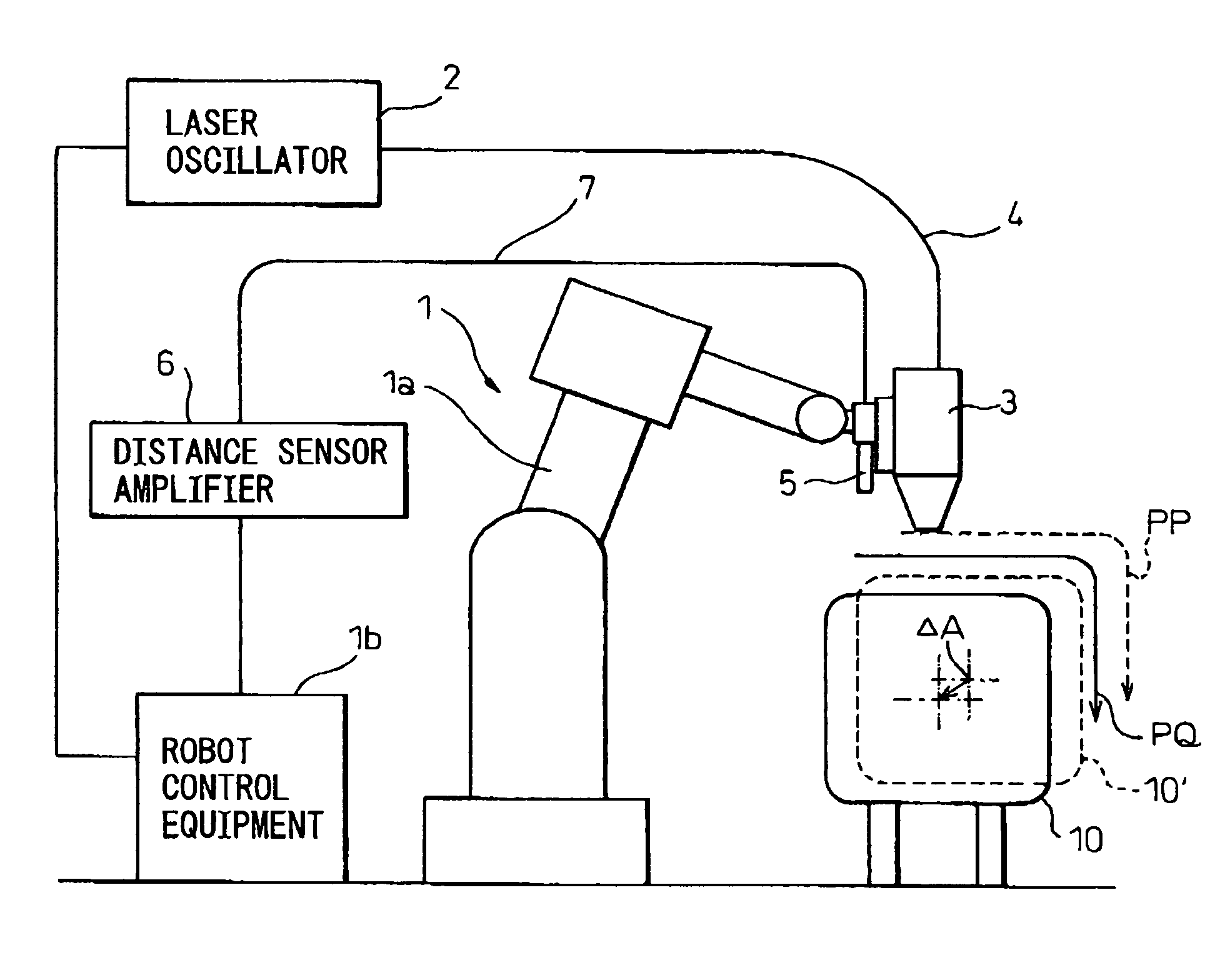
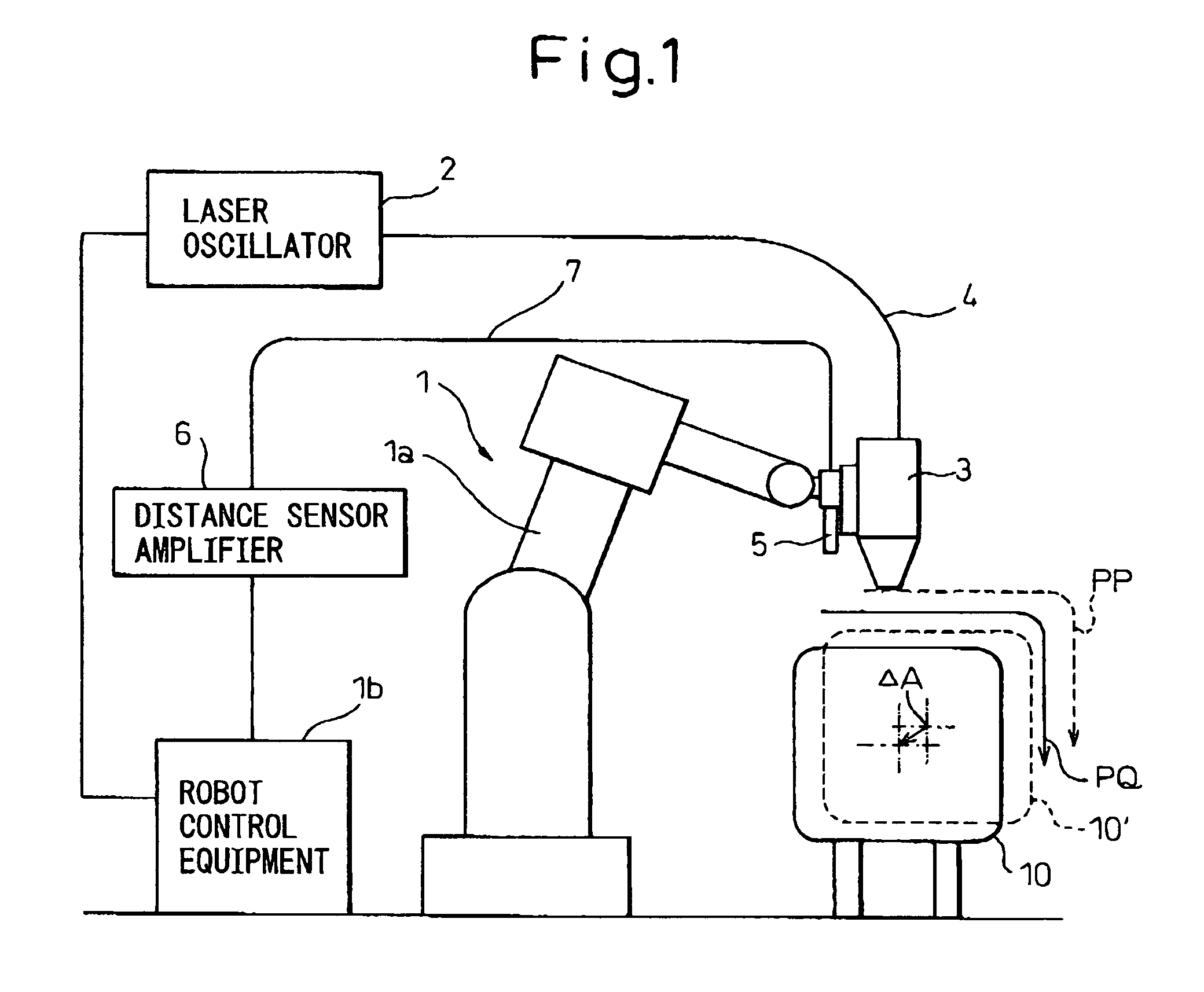
[0028]FIG. 1 schematically shows a robot system to which a correction data checking system in accordance with the present invention can be adapted. The robot system uses a robot 1 to machine a workpiece 10, which is an object to be machined, with laser light. A laser machining head 3 that is a work tool is attached to the distal end of a robot arm included in a robot mechanism 1a. The laser machining head 3 and a laser oscillator 2 are linked by an optical fiber 4.

[0029]Moreover, a distance sensor 5 is attached together with the laser machining head 3 to the distal end of the robot arm included in the robot mechanism 1a. An output of the distance sensor 5 is transferred to a distance sensor amplifier 6 over a cable 7. An output of the distance sensor amplifier 6 is transferred to a robot control equipment 1b.

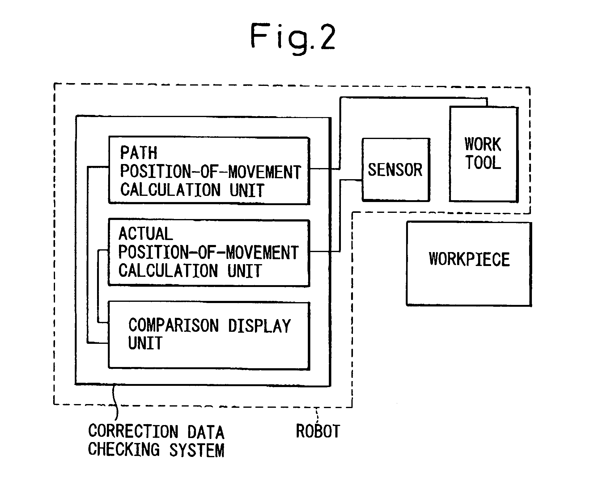
[0030]FIG. 2 is a block diagram showing the fundamental configuration of a correction data checking system in accordance with the present invention. The correction data checkin...


PUM


Abstract

Provided is a correction data checking system, for robots, which makes it easy to reveal the cause of a machining defect. A laser machining head and a distance sensor or a sensor for detecting a work line are attached to the distal end of a robot arm. A robot is driven based on a teaching program, and a copying control technique is implemented based on information sent from the sensor so that the distance between the laser machining head and a workpiece will be equal to a set value. A path of taught positions of the laser machining head and a path of actual positions thereof are displayed in comparison with each other on a display of a teaching console or the like. Moreover, the difference between the taught position and actual position is calculated and displayed. As both the position commanded by the teaching program and the actual position derived from the copying control technique are displayed, if a machining defect occurs, the machining defect is checked to see if it is a problem attributable to the sensor or a problem attributable to the workpiece or a jig. The cause of the machining defect is then revealed. Consequently, the cause of a machining defect can be quickly revealed and dealt with at a working site.

Description

BACKGROUND OF THE INVENTION[0001]1. Field of the Invention[0002]The present invention relates broadly to a robot and, in particular, is concerned with a correction data checking system for robots that perform work while correcting a path, which is commanded by a teaching program, using a sensor.[0003]2. Description of the Related Art[0004]In recent years, the number of fields in which robots are utilized has increased with the advent of more intelligent industrial robots. One of the uses of an intelligent industrial robot is a use based on a copying control technique according to which a height sensor for detecting a distance or a sensor for detecting the position of a work line on a workpiece using a laser light projector and a camera is employed in a robot in order to correct the motion of the robot, which is usually done based on a playback control technique, in line with the shape of the workpiece, that is, an object of the work.[0005]Regarding a copying control technique for co...

Claims


Application Information

Patent Timeline
Patent Type & Authority Patents(United States)
IPC IPC(8): G06F19/00B25J9/16G05B19/4063G05B19/404
CPCB25J9/1684G05B2219/4705
Inventor WATANABE, ATSUSHIOKUDA, MITSUHIRO
Owner FANUC LTD
Learn More