
Fault-tolerant three-level inverter

a three-level inverter, fault-tolerant technology, applied in the direction of dc-ac conversion without reversal, emergency protective circuit arrangement, automatic disconnection emergency protective arrangement, etc., can solve the problem of driving motor to impart an unequal torque to the flywheel, add to the price of the inverter, and accumulate charge at the mid-point between the two dc linking capacitors

Inactive Publication Date: 2006-12-05
THE BOEING CO
View PDF5 Cites 33 Cited by
  • Summary
  • Abstract
  • Description
  • Claims
  • Application Information

AI Technical Summary

Benefits of technology

The patent describes a method for driving a three-level inverter that has a neutral point and is clamped. The inverter has multiple nodes and switches. The method checks for faults in the inverter and automatically activates predetermined switches to provide three-phase electrical power at the output nodes. The invention uses redundancy in the inverter to ensure that the resulting phase angles are the same as in the unfaulted operation, although the magnitude may be reduced. The technical effect of this method is to improve the reliability and stability of the three-level inverter.

Problems solved by technology

Such inverters require complex control circuitry, each of the redundant switches add to the price of the inverter, and the charge at the mid-point between the two DC linking capacitors can accumulate when switching is not balanced.
In many applications, including for example, energy storage flywheels coupled to synchronous motors, failure of the inverter will cause the driving motor to impart an unequal torque to the flywheel.
Such unequal torque, especially at very high revolution rates, might be catastrophic to the flywheel.
However, the inverters will only work as long as the switching components within them will work.
However, without a driver that will quickly recognize a fault, in turn, disabling one of two switching paths, diverting current only through valid switches at appropriate voltages, the redundancy of the design is not exploited.
The fault-caused imbalances can easily upset the driven load.

Method used


Image

  • Fault-tolerant three-level inverter
  • Fault-tolerant three-level inverter
  • Fault-tolerant three-level inverter

Examples


Embodiment Construction

[0027]By way of overview, a method for driving a neutral point clamped three-level inverter is provided. In one exemplary embodiment, DC current is received at a neutral point-clamped three-level inverter. The inverter has a plurality of nodes including first, second and third output nodes. The inverter also has a plurality of switches. Faults are checked for in the inverter and predetermined switches are automatically activated responsive to a detected fault such that three-phase electrical power is provided at the output nodes.

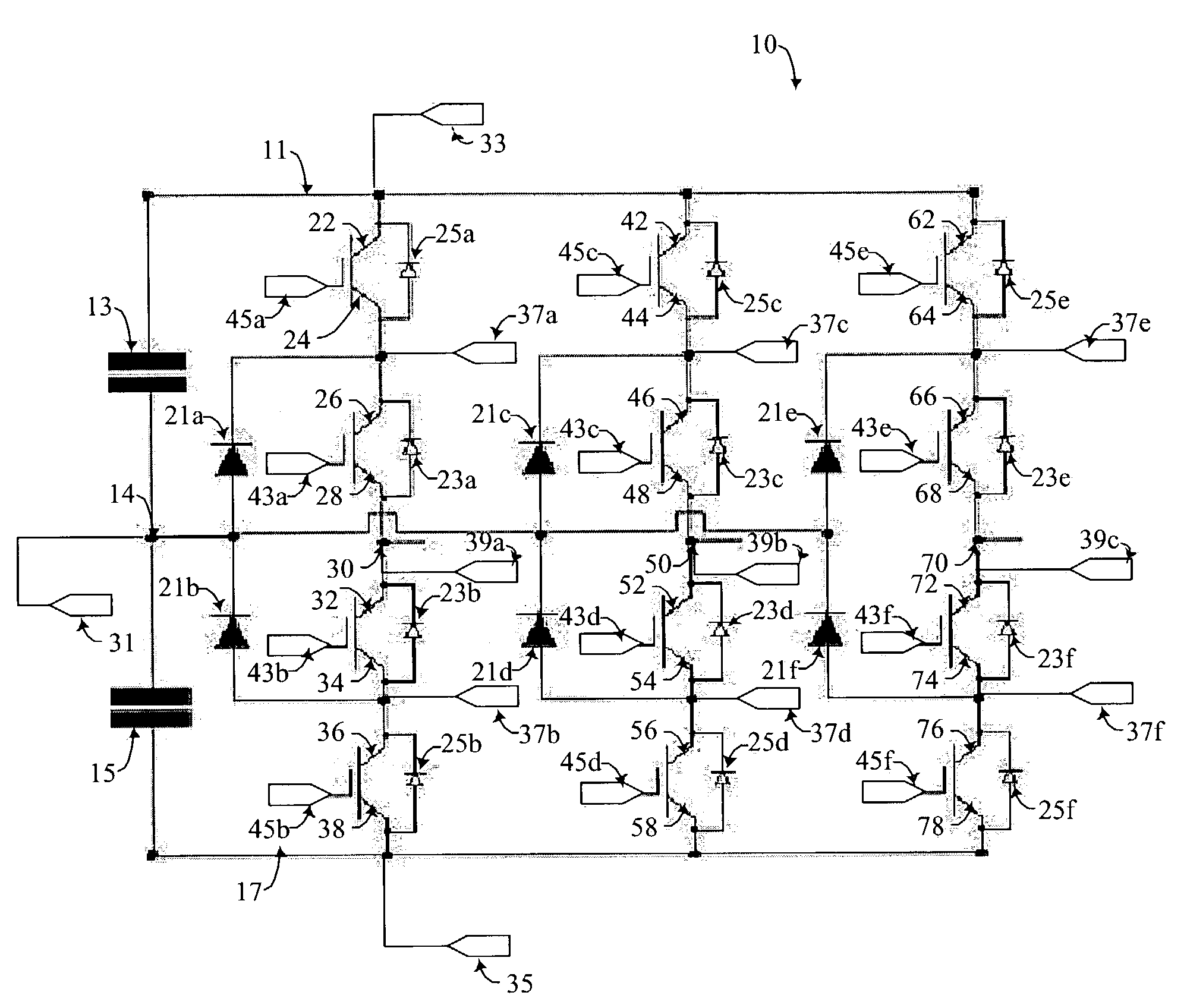
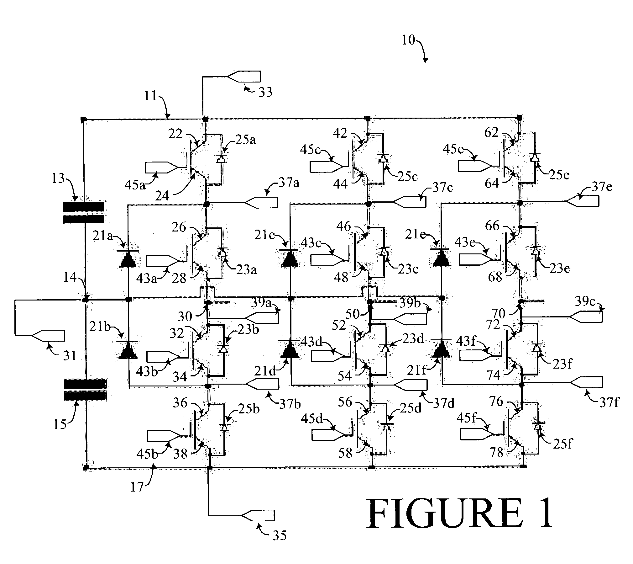
[0028]Referring to FIG. 1 DC linking capacitors 13 and 15 are connected in series and separate a positive DC bus node 11 from a negative DC bus node 17. The capacitors 13 and 15 define a neutral point 14 between the capacitors 13 and 15 that is capable of accepting and storing either positive or negative charge. The neutral point 14 allows the inverter to treat the DC bus nodes 11 and 17 as though there were two equal DC sources connected in series defining ...


PUM


Abstract

A method for driving a neutral point clamped three-level inverter is provided. In one exemplary embodiment, DC current is received at a neutral point-clamped three-level inverter. The inverter has a plurality of nodes including first, second and third output nodes. The inverter also has a plurality of switches. Faults are checked for in the inverter and predetermined switches are automatically activated responsive to a detected fault such that three-phase electrical power is provided at the output nodes.

Description

STATEMENT OF GOVERNMENT INTEREST[0001]This invention was made with government support under contract number DE-FC36-99-GO-10285 awarded by the Department of Energy. The U.S. Government has certain rights in this invention.FIELD OF THE INVENTION[0002]This invention relates generally to power conversion and, more specifically, to three-level inverter modulation.BACKGROUND OF THE INVENTION[0003]Inverters are utilized in AC motor drive, utility interface, and an uninterruptible power supply (“UPS”) applications as a means for converting DC to AC electrical power. A traditional inverter generates a low frequency output voltage with controllable magnitude and frequency by programming high-frequency voltage pulses. The high frequency voltage pulses open and close switches to expose a load to pulses of DC current. An inverter of this type is said to be using pulse width modulation (“PWM”). Timing, duration, and voltage of the pulses simulate the peaks and troughs of traditional sinusoidal a...

Claims


Application Information

Patent Timeline
Patent Type & Authority Patents(United States)
IPC IPC(8): H02B1/24H02M1/00H02M7/48H02M7/487
CPCH02M7/487H02M1/32H02M2001/325H02M2007/53876H02M1/325H02M7/53876
Inventor EDWARDS, JOHNXU, LONGYABHARGAVA, BRIJ B.
Owner THE BOEING CO
Learn More