
Safety shield for medical needles

a technology for shielding medical needles and needles, which is applied in the direction of catheters, packaged goods, foodstuffs, etc., can solve the problems of disadvantageous misfire, device manipulation by a practitioner, and difficulty in providing adequate care while following safety procedures, etc., and achieves the effect of effectively and inexpensively protecting the tip of a medical needl

Inactive Publication Date: 2006-12-05
KPR U S LLC
View PDF251 Cites 21 Cited by
  • Summary
  • Abstract
  • Description
  • Claims
  • Application Information

AI Technical Summary

Benefits of technology

The present patent is about a medical needle shield apparatus that can protect the tip of a needle after use. The apparatus includes a collar and a shield that can be extended from a retracted position to an extended position. The collar is mounted on the medical needle device and the shield can enclose the needle after use. The collar has stops that prevent the shield from moving in the wrong direction. The apparatus is effective and inexpensive, and it provides a safer way to use medical needle devices.

Problems solved by technology

Thus, the difficulty in providing adequate care while following safety procedures is often compounded by the patient's physical condition and mental state, such as in bum units and psychiatric wards.
Under such conditions, proper disposal of a used needle, while caring for a patient, is a technological challenge to the state of the art.
These devices, however, require two-handed manipulation from a practitioner.
These devices, however, may disadvantageously misfire, be inadvertently activated or cumbersome to activate.
Further drawbacks of current devices include high manufacturing cost due to complexity and the number of parts.
Thus, these type prior art devices may not adequately and reliably shield needle infusion and / or fluid collection apparatus to prevent hazardous exposure.

Method used


Image

  • Safety shield for medical needles
  • Safety shield for medical needles
  • Safety shield for medical needles

Examples


Embodiment Construction

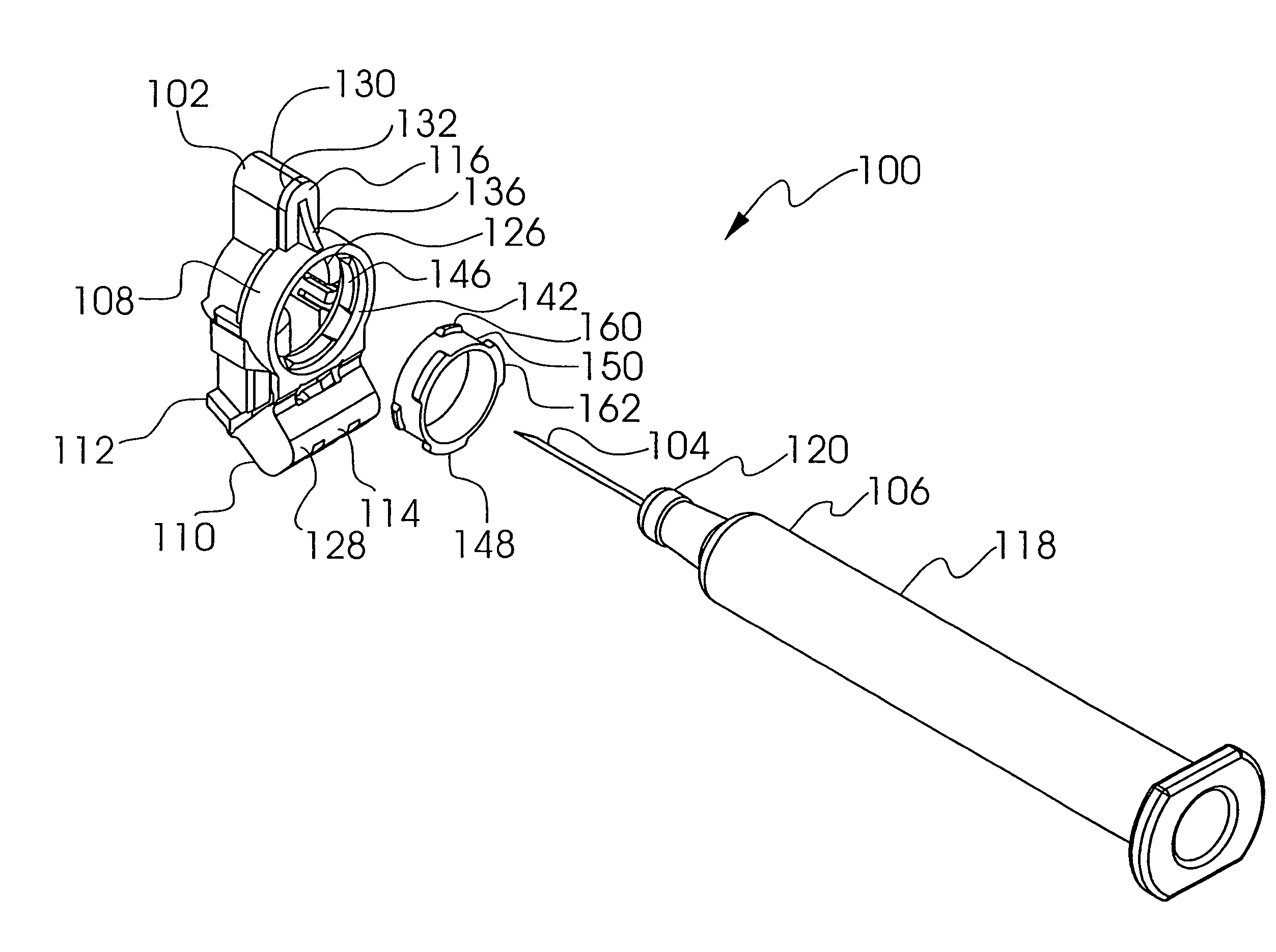
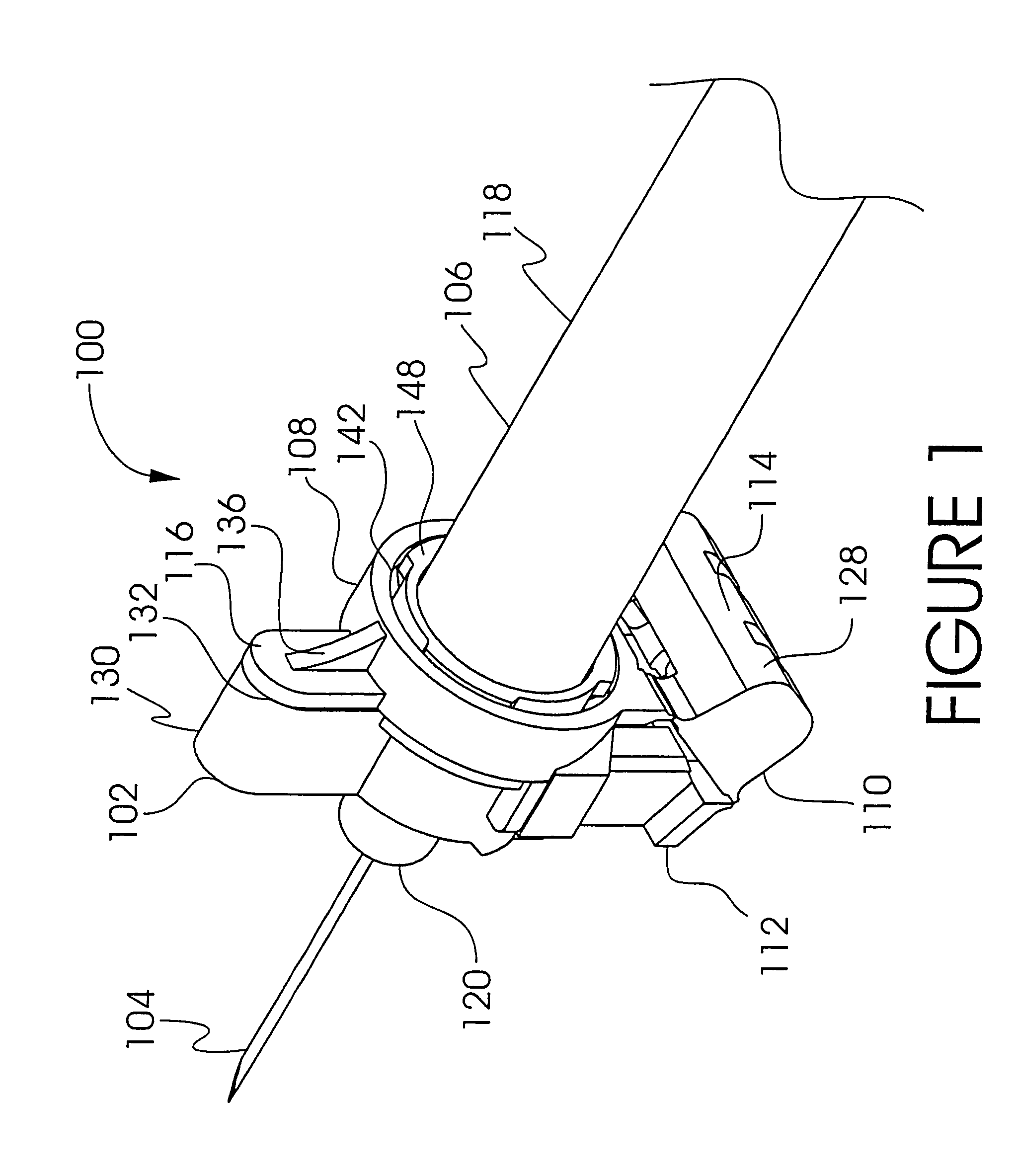
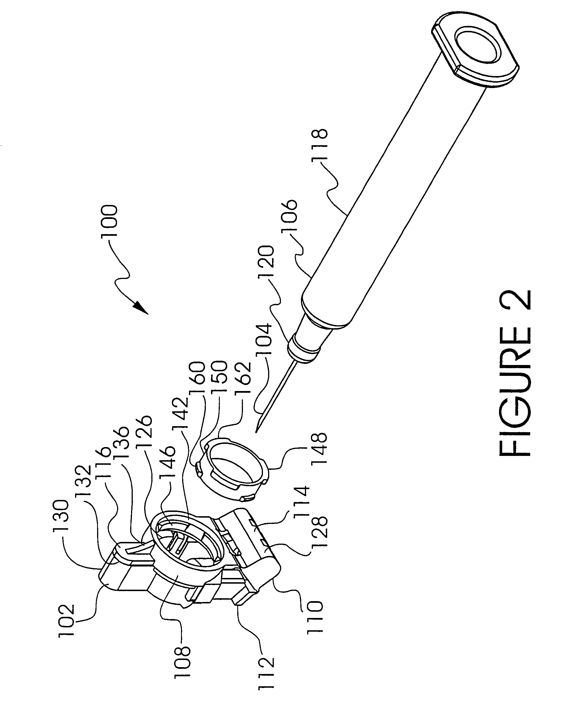
[0033]The exemplary embodiments of the medical needle shield apparatus and the methods of operation disclosed herein are discussed in terms of medical needles for infusion of intravenous fluids, medication infusion and fluid collection, and more particularly, in terms of a medical needle shield device employed with a needle shield apparatus associated with a needle cannula to prevent damage to the needle and possible hazardous exposure to the needle cannula, for example, through an inadvertent needle stick. It is contemplated that the needle cannula may be shielded during use including storage, transport, fluid infusion and / or collection, subsequent thereto, etc. It is envisioned that the present disclosure, however, finds application to a wide variety of cannula needles and devices for the infusion of preventive medications, medicaments, therapeutics, etc. to a subject. It is also envisioned that the present disclosure may be employed for collection of body fluids including those e...


PUM


Abstract

A medical needle shield apparatus is provided that includes a first cylinder, such as, for example, a shield that is extensible from a retracted position to an extended position for enclosing a distal end of a needle of a medical needle device. The shield includes a collar that is mounted to the medical needle device. The shield further includes a proximal portion extending from the collar and a distal portion extending from the proximal portion. The distal portion is configured to enclose the distal end of the needle in the extended position. The proximal portion includes an engagement surface that is engageable to urge the shield from the retracted position to the extended position. The collar includes a guard extending therefrom and is disposed adjacent to the distal portion of the shield in the retracted position such that inadvertent extension of the shield, via engagement of the distal portion, is prevented.

Description

CROSS-REFERENCE TO RELATED APPLICATIONS[0001]This patent application is a continuation-in-part of U.S. Utility patent application Ser. No. 10 / 164,944, filed in the U.S. Patent and Trademark Office on Jun. 6, 2002 now U.S. Pat. No. 7,029,461 by Ferguson et al., which is a continuation-in-part of U.S. Utility patent application Ser. No. 09 / 892,593 filed in the U.S. Patent and Trademark Office on Jun. 27, 2001 by Ferguson et al., which claims priority from U.S. Provisional Patent Application Ser. No. 60 / 275,886 filed in the U.S. Patent and Trademark Office on Mar. 14, 2001 by Thome et al., the entire contents of each of these disclosures being hereby incorporated by reference herein.BACKGROUND[0002]1. Technical Field[0003]The present disclosure generally relates to safety shields for medical needles, and more particularly, to extensible safety shields that employ a manual actuator to configure the safety shield from a retracted position into an extended position.[0004]2. Description of...

Claims


Application Information

Patent Timeline
Patent Type & Authority Patents(United States)
IPC IPC(8): A61M5/32A61B5/15A61M5/158A61M5/31A61M25/06
CPCA61B5/1405A61B5/153A61M5/158A61M5/3243A61M5/3275A61J1/2096A61J2001/201A61J2001/2055A61M5/3129A61M25/0612A61M25/0631A61M2005/1581A61M2005/3139A61M2005/3247A61J1/201A61J1/2055A61B5/15003A61B5/150236A61B5/150244A61B5/150389A61B5/150503A61B5/150595A61B5/150625A61B5/150633A61B5/150587A61B5/150717A61B5/150664
Inventor FERGUSON, F. MARKSMITH, DANIEL K.
Owner KPR U S LLC
Learn More