Adaptive integrated circuit for magnetoresistive sensors

a technology of integrated circuits and magnetoresistive sensors, applied in pulse generators, pulse techniques, instruments, etc., can solve problems such as system failures, limited clock speed, and design problems of peak detectors

Inactive Publication Date: 2006-11-28
HONEYWELL INT INC
View PDF7 Cites 12 Cited by
  • Summary
  • Abstract
  • Description
  • Claims
  • Application Information

AI Technical Summary

Benefits of technology

[0015]All objects, features, and advantages of the present invention will become apparent in the following detailed written description.

Problems solved by technology

This is a benefit because over time contacts can degrade and cause system failures.
However, the design of this peak detector is problematic in terms of its practicable application as a high-resolution, high slew rate tracking and low power device.
A resolution having fine granularity is generally desired to track the peak with maximum real time accuracy but is limited by the clock speed in terms of its ability to track a high slew signal.
This tracking speed versus resolution tradeoff cannot be addressed by increasing the clock speed since, in practical application, a fast settling DAC requires a lower RC time constant and is incompatible with the low power requirements (typically less that 5 mA) of the application specific integrated circuits on which the detector circuits reside.

Method used


Image

  • Adaptive integrated circuit for magnetoresistive sensors
  • Adaptive integrated circuit for magnetoresistive sensors
  • Adaptive integrated circuit for magnetoresistive sensors

Examples


Embodiment Construction

[0022]The particular values and configurations discussed in these non-limiting examples can be varied and are cited merely to illustrate at least one embodiment of the present invention and are not intended to limit the scope of the invention.

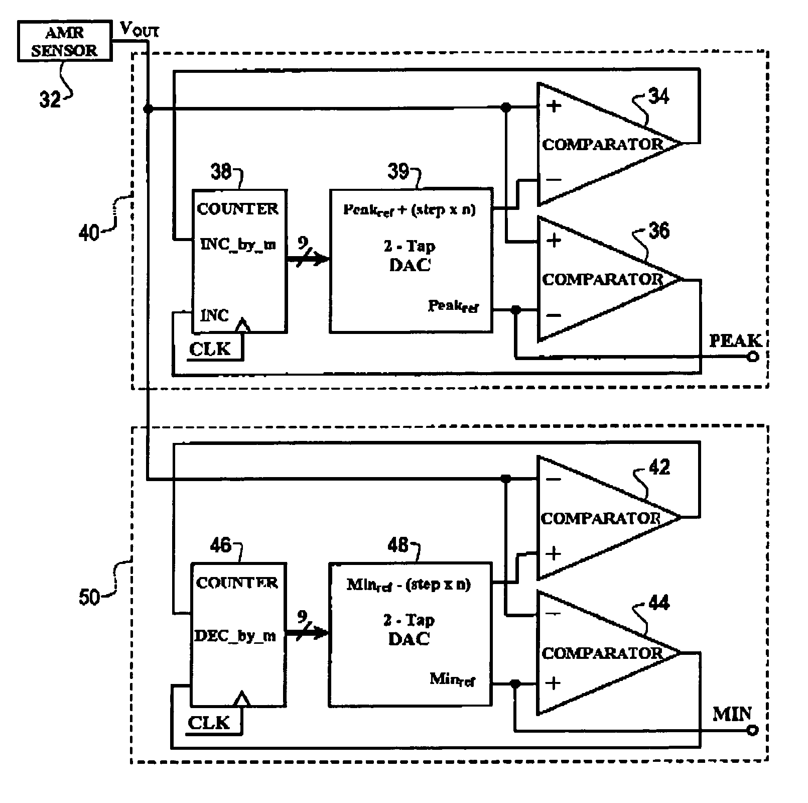
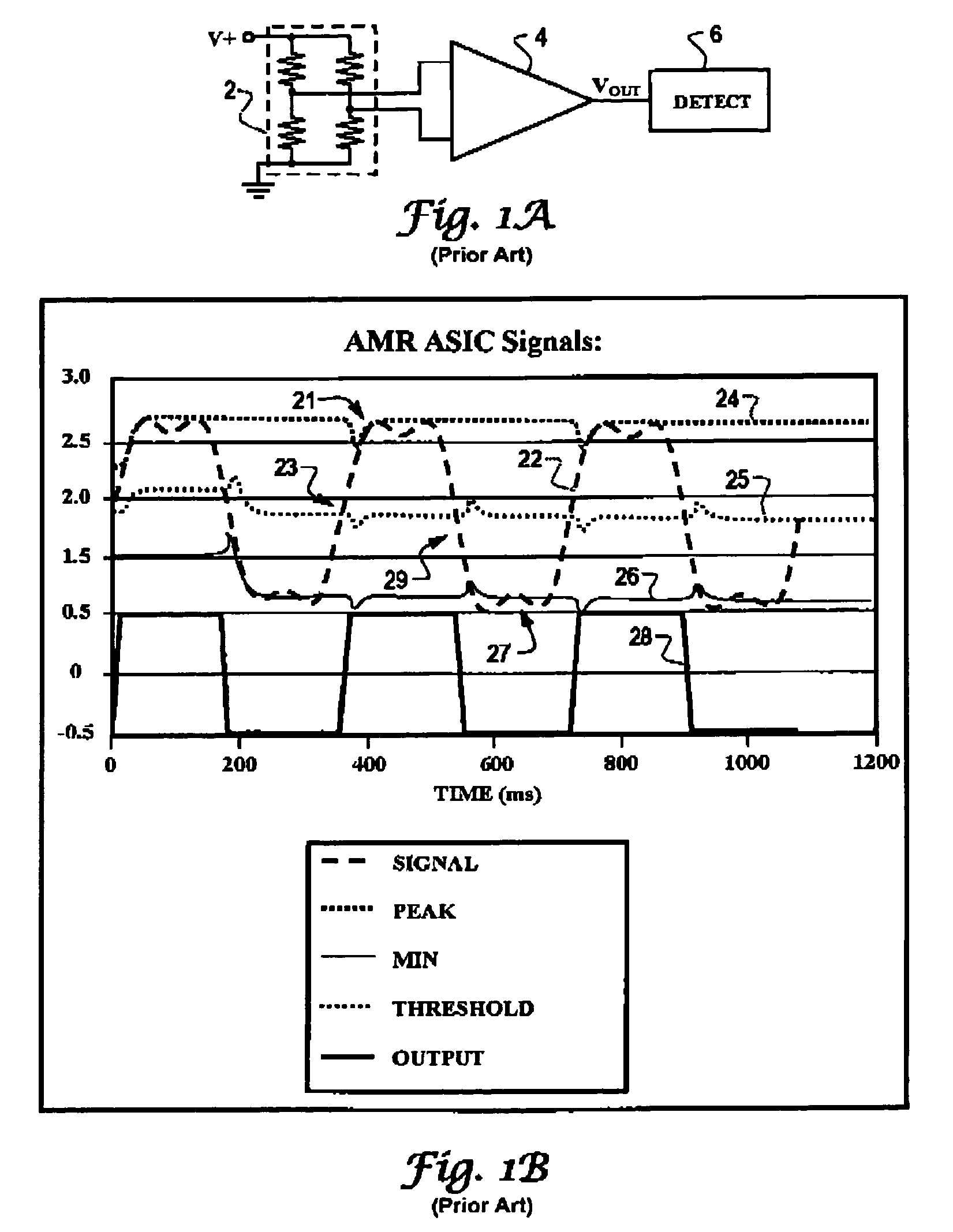
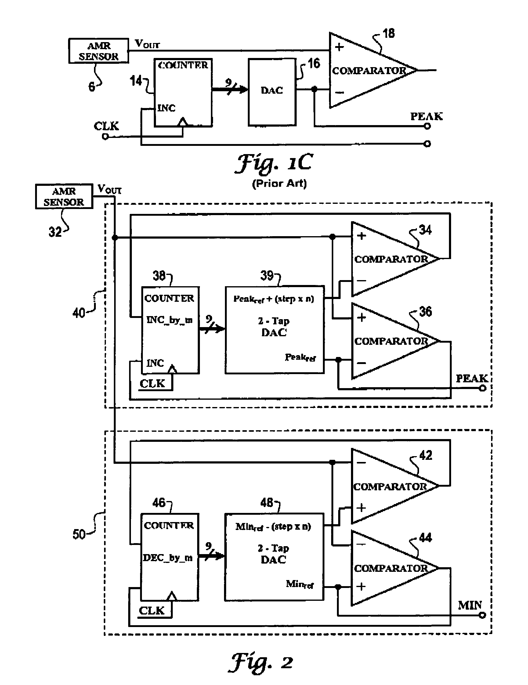
[0023]The present invention is directed to an electronic device, system and method for detecting and tracking a sensed signal in real time. As explained in further detail below with reference to the figures, the present invention is directed to a detector system that tracks the maximum amplitude or peak and / or the minimum amplitude or “min” of a sensed signal such as is used in magnetoresistive sensing systems for tracking a threshold value of a sensor output signal subject to fluctuation or drift. As employed in such systems, the peaks and minimums of a sensed signal are tracked as dynamically adjustable amplitude boundaries from which can be derived a real time mid-signal threshold value of and amplified / conditioned differential signal (i.e. ...


PUM


Abstract

A device, system and method for adaptively tracking amplitude boundary values of a real time sensor output signal. In accordance with the method of the present invention, an amplitude boundary value, which may be a peak or min amplitude value, representing the current amplitude boundary of the sensor output signal is stored within a digital counter. A two-tap DAC is utilized to convert the digitally stored amplitude boundary value into a reference signal level corresponding in amplitude to the amplitude boundary value. The DAC also converts the amplitude boundary value into an offset reference signal level corresponding in amplitude to the amplitude boundary value offset by a specified multiple of the DAC resolution. The reference signal level and offset reference signal are compared with the real time sensor signal and the digitally stored amplitude boundary value is adjusted in accordance with which reference signal level exceeds the real time sensor signal.

Description

TECHNICAL FIELD[0001]Embodiments are generally related to signal detection and processing. The Embodiments are also related to detecting maximum and minimum differential signals such as those generated within a magnetoresistive sensor system. Embodiments are additionally related to a detector device and method for adjustably tracking single ended amplitude peak and / or minimum values of a sensor signal.BACKGROUND OF THE INVENTION[0002]Magnetic sensing devices have many applications, including navigation, position sensing, current sensing, vehicle detection, and rotational displacement. There are many types of magnetic sensors, but essentially they all provide at least one output signal that represents the magnetic field sensed by the device. The Earth, magnets, and electrical currents can all generate magnetic fields. The sensor may be able to detect the presence, the strength, and / or the direction of the magnetic field.[0003]The strength of the magnetic field may be represented by a...

Claims


Application Information

Patent Timeline
Patent Type & Authority Patents(United States)
IPC IPC(8): G01B7/00H03K3/59G01D5/244
CPCG01D5/2448
Inventor HOFFMAN, ERICBUSCH, NICHOLAS F.
Owner HONEYWELL INT INC
Why Eureka
Try Eureka