
Method and system for rotating a turbine stator ring

a technology of stator ring and turbine, which is applied in the direction of stators, machines/engines, liquid fuel engines, etc., can solve the problems of increasing the difficulty of providing suitable nozzle cooling, difficult to achieve extended life, and thermal stress on the nozzles

Inactive Publication Date: 2006-11-28
GENERAL ELECTRIC CO +1
View PDF8 Cites 19 Cited by
  • Summary
  • Abstract
  • Description
  • Claims
  • Application Information

AI Technical Summary

Benefits of technology

"The patent describes a method and system for controlling a turbine's stator ring to prevent damage caused by hot streaks. The system includes a rotator and stator stage that can rotate in response to a control signal. The technical effect of this invention is to improve the efficiency and reliability of turbines by preventing damage caused by hot streaks and optimizing fuel consumption."

Problems solved by technology

Such extended life is difficult to achieve since the nozzles are subject to various differential temperatures during operation, which create thermal stresses on the nozzles.
However, temperature distributions and heat transfer coefficients of the combustion gases channeled through each nozzle vary significantly and increase the difficulty of providing suitable nozzle cooling.
Ensuring that suitable nozzle cooling is provided to each nozzle is a difficult problem.
Location of a hot streak and the dynamics thereof are not easily predictable, thus applying sufficient cooling to areas in the hot streak is problematic and potentially expensive since complex cooling systems are often required.
However, nozzles of a particular stator stage may be exposed to hot streak conditions for extended periods and endure high temperatures and thermal stresses, which shorten nozzle life.
Designing a worst-case nozzle capable of extended exposure to hot streak conditions requires additional expense and / or cooling flow requirements.
Furthermore, maintenance practices requiring routine replacement or relocation of nozzles add to both expense and system down time, and the need for additional cooling flow diminishes turbine performance.

Method used


Image

  • Method and system for rotating a turbine stator ring
  • Method and system for rotating a turbine stator ring
  • Method and system for rotating a turbine stator ring

Examples


Embodiment Construction

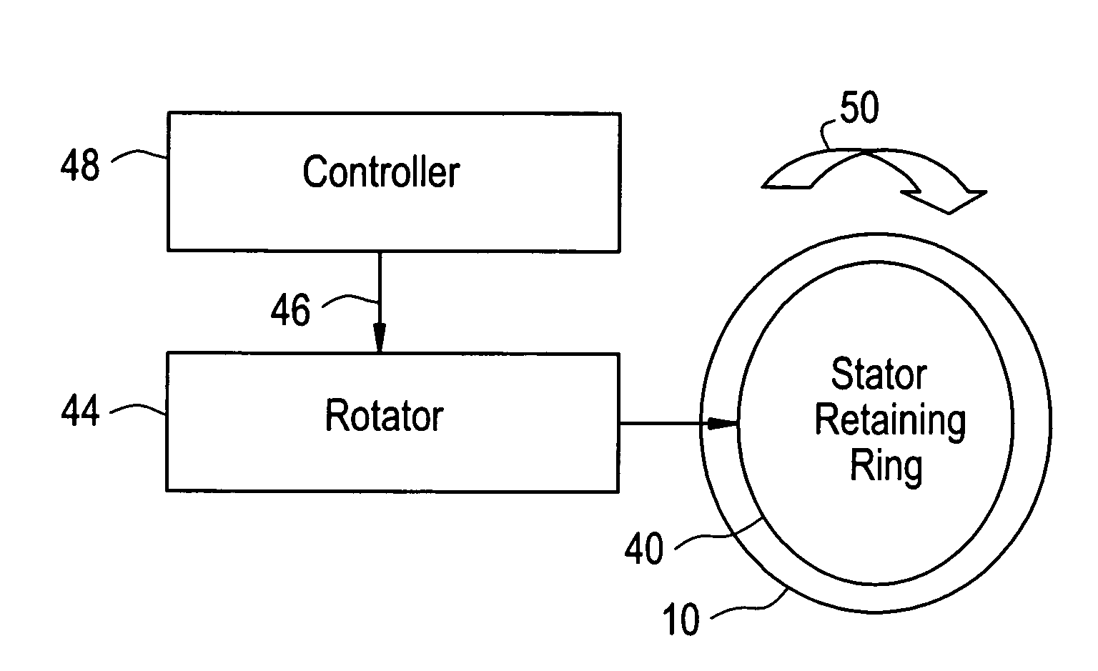
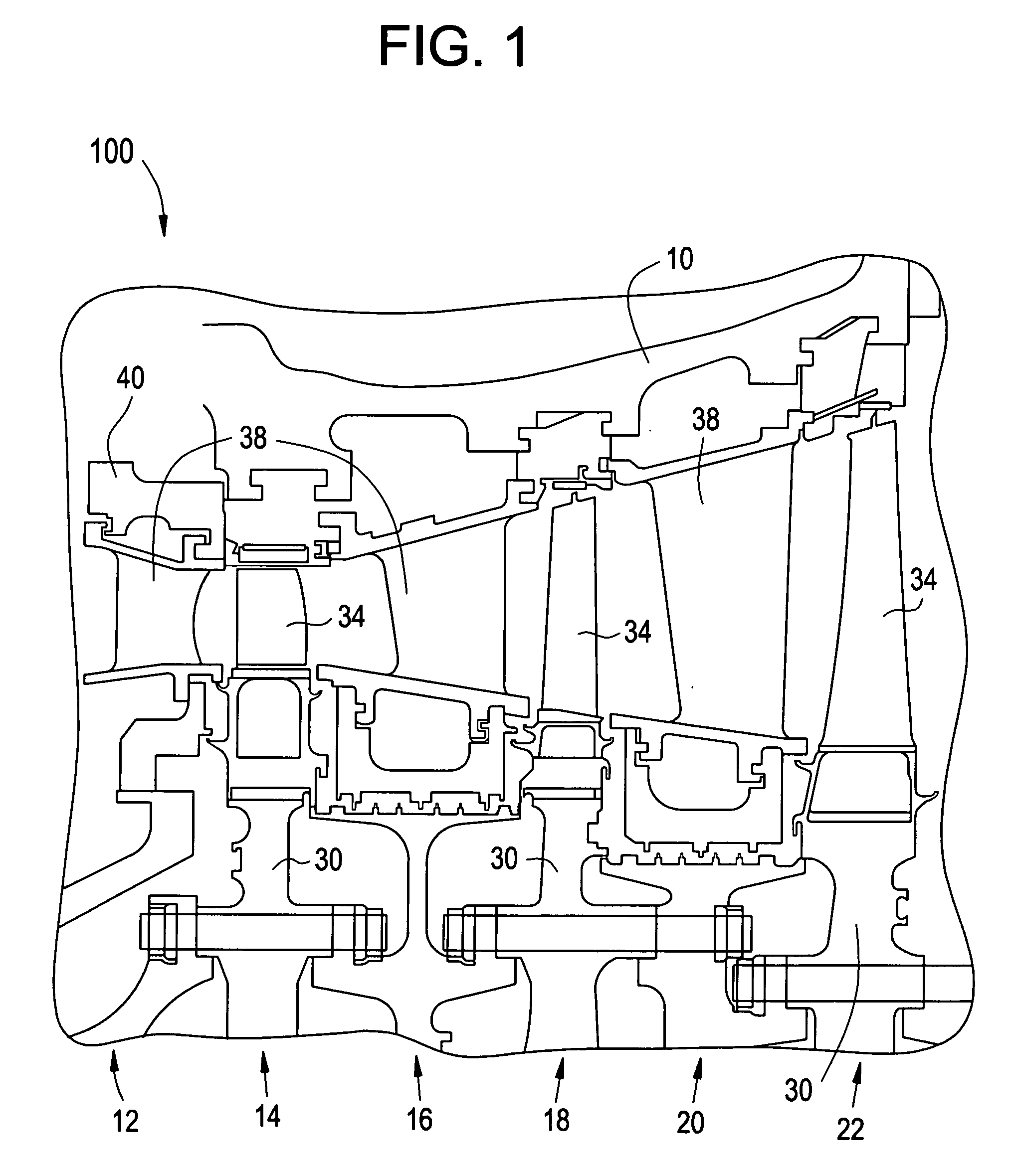
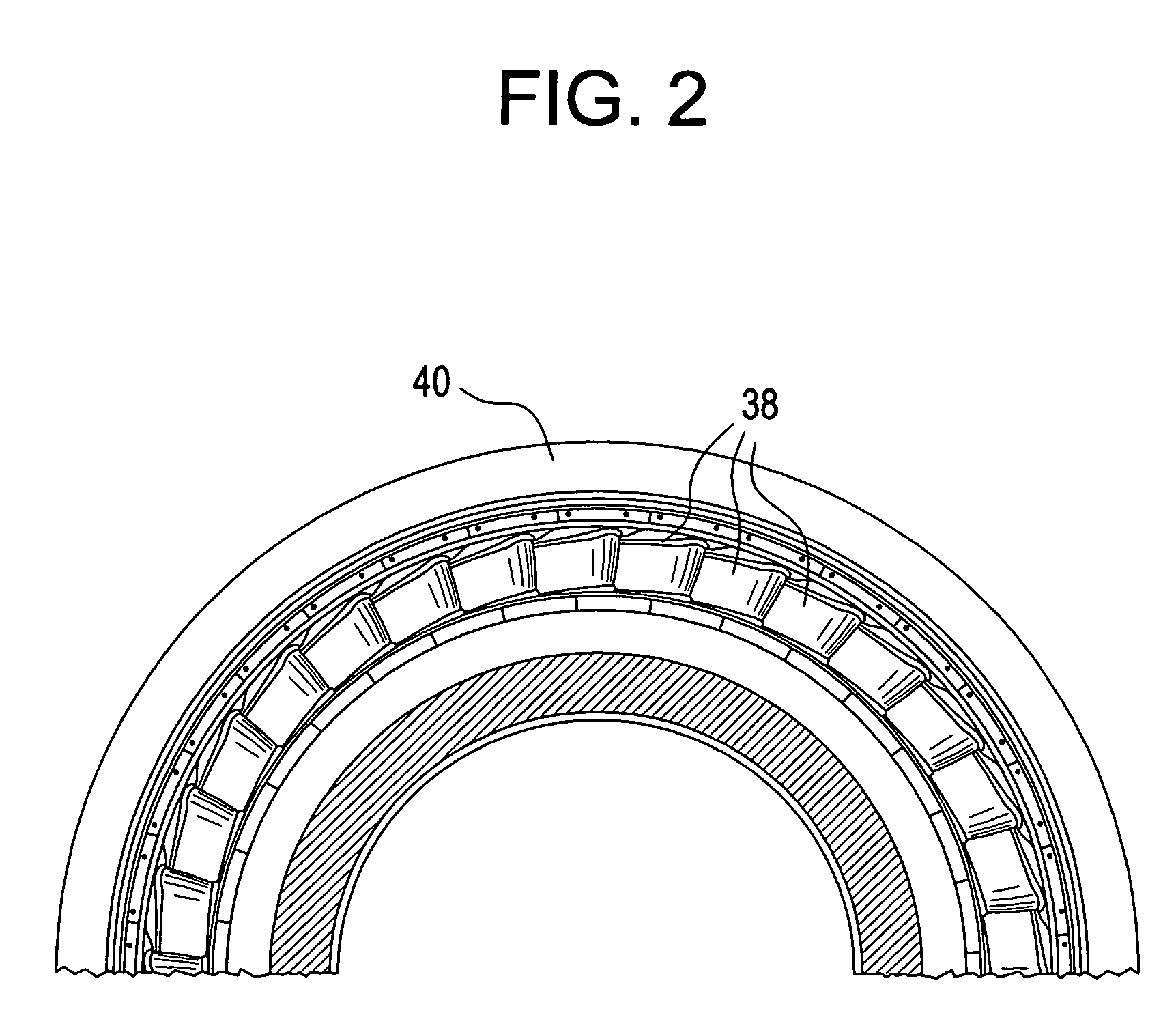
[0018]FIG. 1 is a sectional view of a turbine taken along a longitudinal axis of the turbine according to an exemplary embodiment. FIG. 2 is a portion of a section cut of a turbine taken along a radial axis showing a perspective view of a turbine stator stage according to an exemplary embodiment. Referring to FIGS. 1 and 2, the turbine 100 includes a turbine casing 10, a first stage stator 12, a first stage rotor 14, a second stage stator 16, a second stage rotor 18, a third stage stator 20 and a third stage rotor 22. Stator and rotor stages 12 through 22 are alternately arranged within the turbine casing 10, such that each of the first, second and third stage stators 12, 16 and 20 is disposed proximate to a corresponding one of the first, second and third stage rotors 14, 18 and 22, respectively. Although the turbine 100 of this exemplary embodiment includes three stages of both stator and rotor, it should be noted that any number of stages may be used in employing the principles d...


PUM


Abstract

A method for distributing effects of a circumferential hot streak condition in a turbine includes communicating a control signal to a rotator moving a stator ring with the rotator in response to the control signal.

Description

BACKGROUND OF THE INVENTION[0001]The present invention relates to gas turbine engines, and, more specifically, to a stator of a gas turbine engine.[0002]In a gas turbine engine, air is pressurized in a compressor and mixed with fuel and ignited in a combustor for generating combustion gases having high temperatures. Energy is extracted from the combustion gases in stages of a turbine. The turbine powers the compressor and produces useful work, such as driving a generator to produce power, for example.[0003]Since turbines are continuously exposed to the combustion gases during operation, cooling of turbine components is required. Bleeding a portion of the pressurized air from the compressor and channeling it through the turbine components often provides cooling air to accomplish cooling of turbine components. However, the cooling air is at a premium with respect to overall turbine performance, since useful work has already been done to the cooling air in the compressor. Therefore, it...

Claims


Application Information

Patent Timeline
Patent Type & Authority Patents(United States)
IPC IPC(8): F01D17/00
CPCF01D9/041F01D25/12F01D25/36F05D2270/112F05D2260/80F05D2270/11F05D2240/128F05D2250/411
Inventor JACKS, CURTIS JOHN
Owner GENERAL ELECTRIC CO
Learn More