
Downhole cutting tool and method

Inactive Publication Date: 2006-11-28
WEATHERFORD TECH HLDG LLC
View PDF11 Cites 11 Cited by
  • Summary
  • Abstract
  • Description
  • Claims
  • Application Information

AI Technical Summary

Benefits of technology

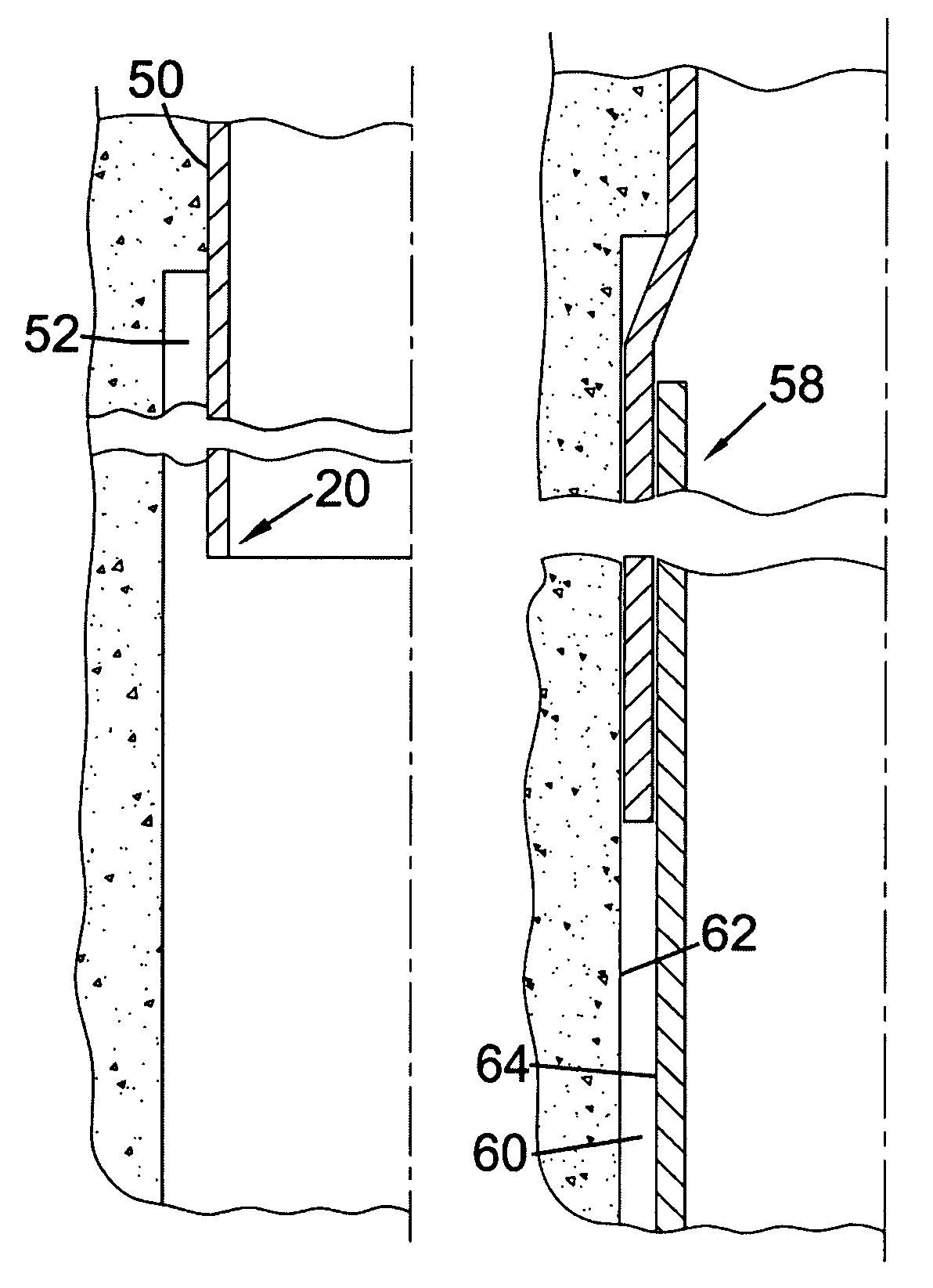
[0020]Locating the bore-lining tubing in the borehole with part of the tubing in the enlarged borehole part provides an enlarged gap between an outer surface of the tubing part and a wall of the borehole. This allows for subsequent expansion of the tubing into the gap, or location of a second bore-lining tubing in the borehole with an end in the gap and overlapping the first tubing, as will be described below.
[0083]The second tubing may be run into the first tubing and suspended from a string of support tubing extending to surface. This provides a connection with the second tubing which facilitates movement of the second tubing to a desired location following expansion of the second tubing.

Problems solved by technology

This traditional method of casing a borehole is both time-consuming and costly as it involves locating multiple lengths of casing in the borehole, each extending from the wellhead.
This employs long lengths of expensive metal casing and large volumes of cement.
Furthermore, in the event of a problem being encountered during drilling of the borehole, such as drilling fluid being lost into a fractured or highly permeable formation, it is necessary to conduct remedial operations to overcome such problems.
Although this eventuality is allowed for during planning of the well, it is generally undesired and too many such occurrences can have a significant effect upon the final diameter of the borehole and thus the ability to conduct completion procedures.
However, various problems have been encountered.
This is not possible with existing casing strings because the casing is cemented into the wellbore.
However, the liner shoe cannot be used in existing well boreholes cased and cemented as described above.

Method used


Image

  • Downhole cutting tool and method
  • Downhole cutting tool and method
  • Downhole cutting tool and method

Examples


Embodiment Construction

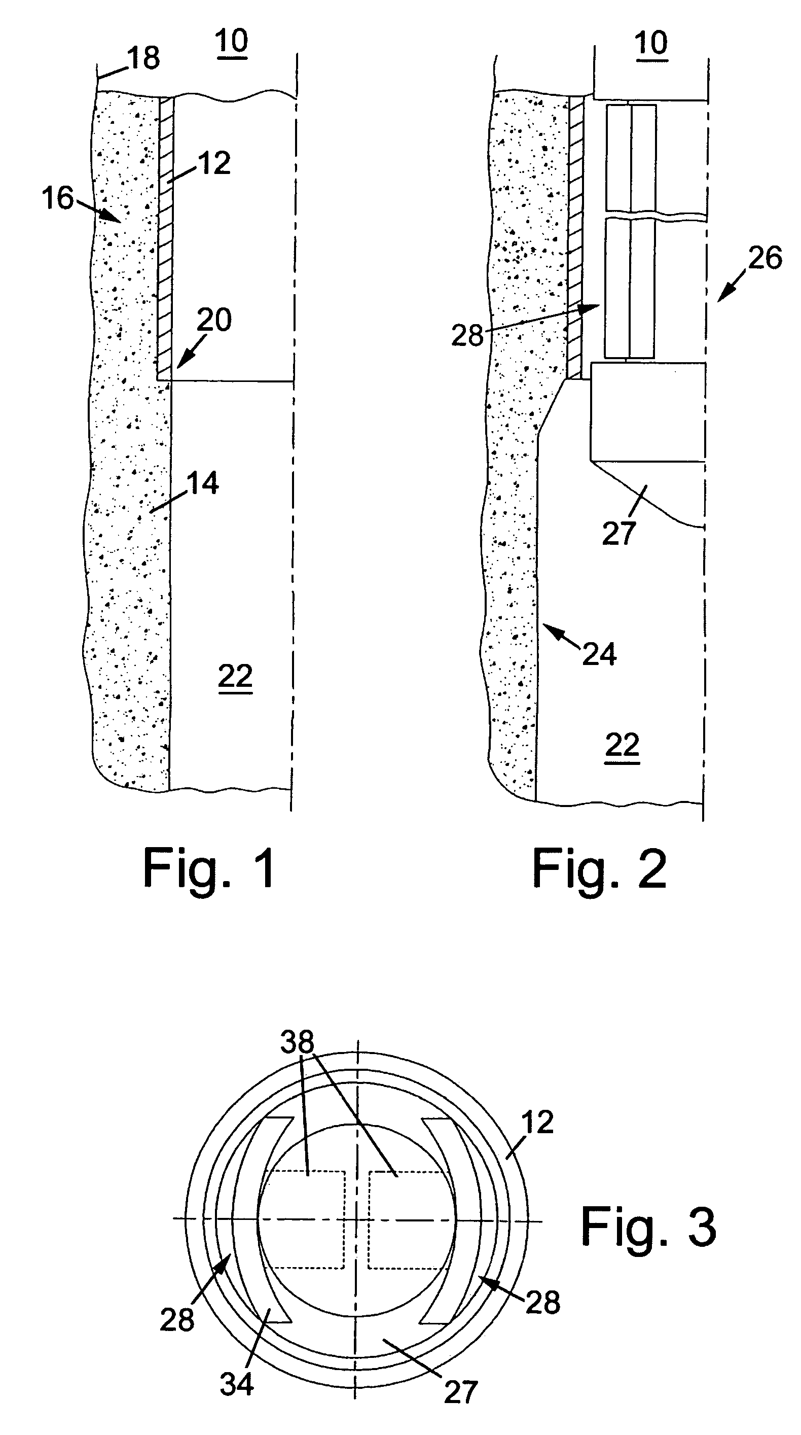
[0106]Turning firstly to FIG. 1, there is shown a schematic half-sectional illustration of a borehole 10 which has been partially lined with a first tubing in the form of a borehole casing 12. A shoe 20 of the casing is shown in the figures, which is the lowermost or deepest section of casing 12 in the borehole. The casing 12 has been cemented in the borehole 10 by pumping cement 14 into an annulus 16 defined between the borehole wall 18 and the casing 12 in first steps of a method of forming a tubing-lined borehole. FIG. 1 shows the borehole after the cement 14 has set and the borehole 10 continued by drilling a smaller diameter bore extending from an end of the casing shoe 20, this smaller diameter bore portion being initially unlined and indicated by reference numeral 22.

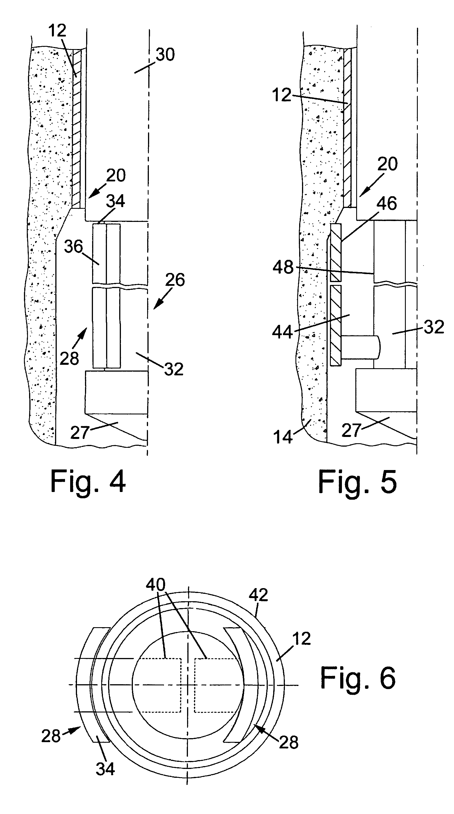
[0107]The unlined portion 22 of the borehole is then enlarged in the region 24 axially below the end 20 of the casing 12, as shown in FIG. 2, using a conventional underreaming tool, or an underreaming tool of the...


PUM


Abstract

There is disclosed a method of forming a tubing lined borehole, the method comprising the steps of forming a borehole; enlarging part of the borehole by increasing the diameter thereof; and locating bore-lining tubing in the borehole with at least part of the tubing located in the enlarged part of the borehole, and a corresponding a tubing lined borehole.There is also disclosed a downhole cutting tool comprising a tool body; and at least one cutting element mounted for radial movement with respect to the tool body between a retracted position and a cutting position, in the cutting position the cutting element describing a cutting diameter and an axially extending annular space inwardly of the cutting element, and a corresponding method.

Description

CROSS-REFERENCE TO RELATED APPLICATIONS[0001]This application claims benefit of Great Britain patent application serial number GB 0230189.3, filed Dec. 27, 2002, which is herein incorporated by reference.BACKGROUND OF THE INVENTION[0002]1. Field of the Invention[0003]The present invention relates to a method of forming a tubing lined borehole and to a downhole cutting tool. In particular, but not exclusively, the present invention relates to a downhole cutting tool for use in enlarging an existing borehole. The invention also relates to a method of enlarging a borehole.[0004]2. Description of the Related Art[0005]In the oil and gas exploration and production industry, it is a common practice to drill a borehole to a desired depth for recovering well fluids from hydrocarbon-bearing rock formations. Logging procedures are carried out both before and during drilling of the borehole to determine physical characteristics of the rock formations. Typically, the borehole is drilled to a fir...

Claims


Application Information

Patent Timeline
IPC IPC(8): E21B19/16E21B7/28E21B10/32E21B43/10
CPCE21B7/28E21B10/32E21B43/103E21B43/105E21B43/10
Inventor MACKAY, ALEXANDER CRAIG
Owner WEATHERFORD TECH HLDG LLC
Learn More