Modeling metastability in circuit design

a circuit design and metastability technology, applied in the field of circuit design flow, can solve problems such as disruption or inability to operate accurately, flip-flop entering a state of unpredictable output, disruption particularly evident, etc., and achieve the effect of stable transition of d

Active Publication Date: 2006-11-21
TEXAS INSTR INC
View PDF1 Cites 38 Cited by
  • Summary
  • Abstract
  • Description
  • Claims
  • Application Information

AI Technical Summary

Problems solved by technology

When this occurs from a first clock domain to a second clock domain, the timing of circuitry operating according to the second clock domain may be disrupted or operate inaccurately due to a signal that is still timed according to the first clock domain.
This disruption is particularly evident in the context of a flip-flop in one clock domain that attempts to process a signal from a different clock domain.
If this occurs, it is said that there is either a setup or hold time violation, and as a result the flip-flop enters a state where its output is unpredictable.
As a result, metastability, which often arises from asynchronous connectivity as described above, is not addressed during the RTL design flow.
Moreover, once designated as a false path, the timing on the path is turned off, negating the whole point of gate level simulations with timing.
When violation occurs, the effect of that data as it further propagates through the design is no longer meaningful nor analyzed and the simulation will in likelihood be invalidated.
Thus, there is no accountability for correct functionality at either the RTL or gate level simulations as to the effects of metastability.
As a result of the preceding, it is not uncommon for integrated circuits to be constructed according to a design that was developed according to the prior art, only to learn after the construction of the device that it does not operate properly due to metastability.

Method used


Image

  • Modeling metastability in circuit design
  • Modeling metastability in circuit design
  • Modeling metastability in circuit design

Examples


Embodiment Construction

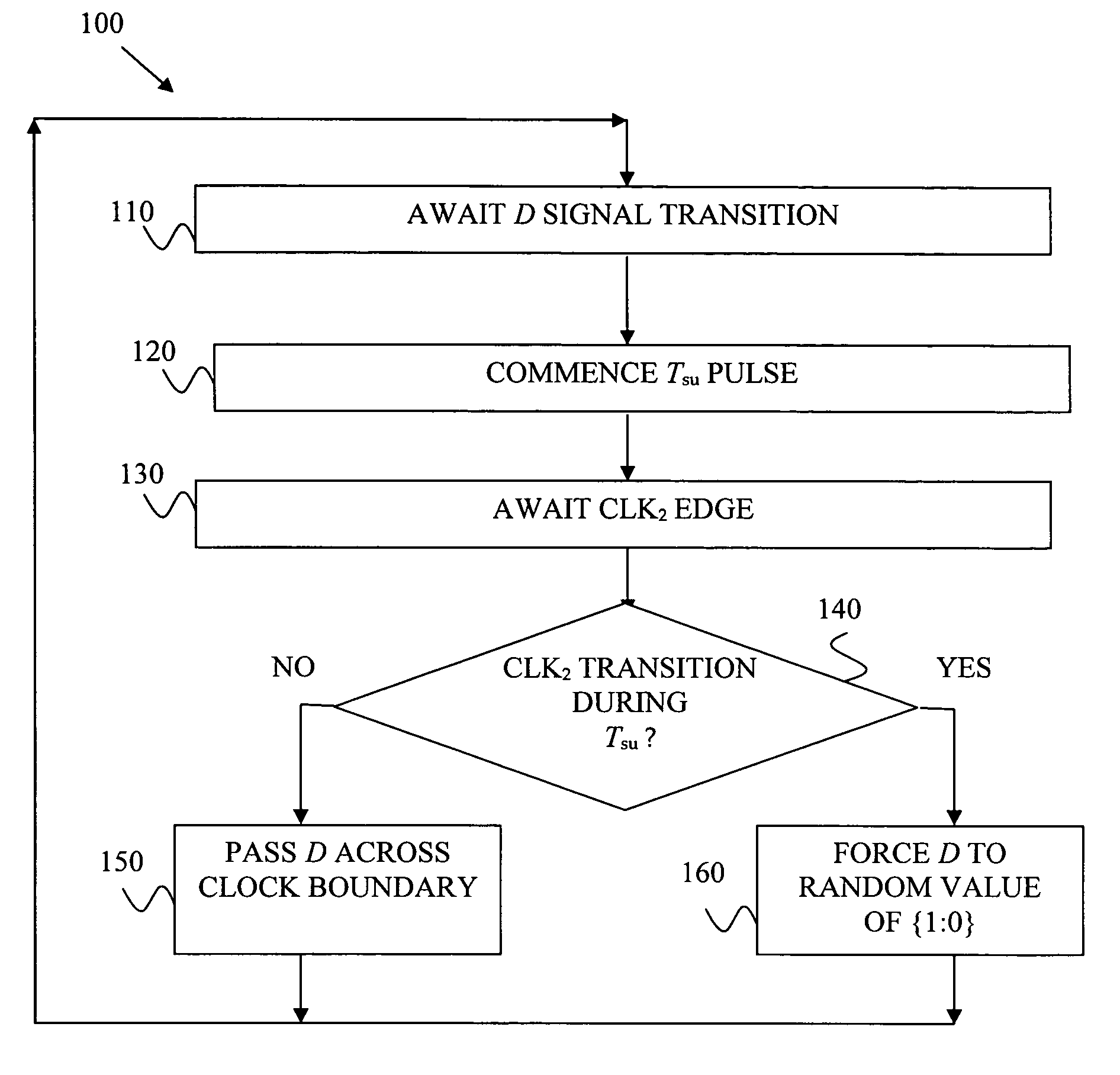
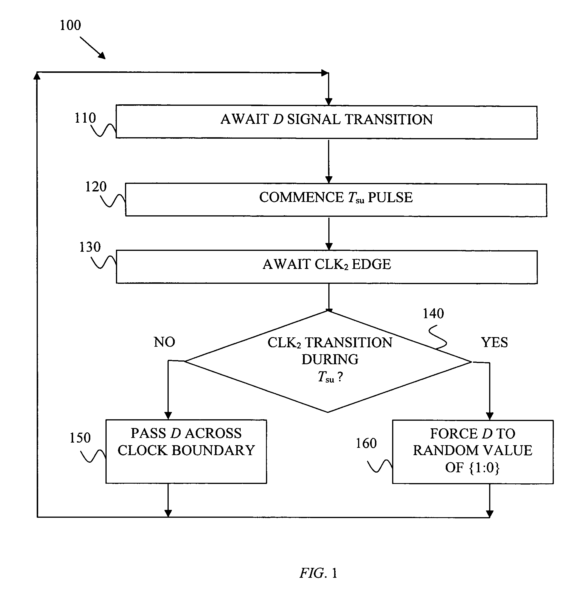
[0017]In accordance with the preferred embodiments, various code is included in either or both of the circuit functional level (e.g., register transfer level (“RTL”) or any other language used to describe and model circuitry) or gate simulation design flow so as to improve these design flows in the context of metastability. To better appreciate these aspects, the discussion below first address the functional aspect, using RTL as a preferred example, and is then followed with the gate level aspect.

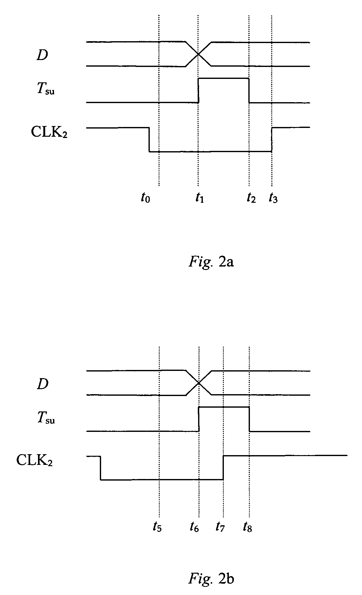
[0018]In connection with improving the RTL design flow so as to provide for improved testing with the possibility of metastability, the preferred embodiments include sufficient code so as to provide a behavioral form of potential metastability at the edge between RTL functions where a signal will cross from one clock domain to another. This code is further described below, but first various observations are noteworthy. As a first observation, note that in circuit design, often a so-called s...


PUM


Abstract

A computer program (100, 200) encoded in a computer-programmable medium, and for causing a computer to perform circuit design. The code causes the computer to perform a set of steps. The steps comprise describing a first set of circuitry and describing a second set of circuitry. The steps also comprise describing a digital signal for passing from the first set of circuitry to the second set of circuitry and detecting (230) transitions of the digital signal with respect to a timing constraint (240) of at least a portion of the second set of circuitry. Lastly, the steps comprise, responsive to detecting metastability with respect to timing of a transition of the digital signal relative to the timing constraint of at least a portion of the second set of circuitry, forcing (160) the digital signal to a random value and passing the random value to the second set of circuitry.

Description

CROSS-REFERENCES TO RELATED APPLICATION[0001]Not Applicable.STATEMENT REGARDING FEDERALLY SPONSORED RESEARCH OR DEVELOPMENT[0002]Not Applicable.COPYRIGHT[0003]A portion of the disclosure of this patent document contains material which is subject to (copyright or mask work) protection. The (copyright or mask work) owner has no objection to the facsimile reproduction by anyone of the patent document or the patent disclosure, as it appears in the Patent and Trademark Office patent file or records, but otherwise reserves all (copyright or mask work) rights whatsoever.BACKGROUND OF THE INVENTION[0004]The present embodiments relate to circuit design flow and are more particularly directed to including consideration of metastability into the circuit design flow.[0005]Circuit design flow includes at least two general steps. Typically using some combination of hardware and / or software, in a first step the designer creates a functional behavioral model such as by way of example in a register ...

Claims


Application Information

Patent Timeline
Patent Type & Authority Patents(United States)
IPC IPC(8): G06F17/50
CPCG06F17/5022G06F17/5045G06F30/33G06F30/30G06F30/3308G06F2119/12
Inventor CHARD, GARY F.KOYUNCU, OSMANKOH, T-PINN R.DONDERSHINE, STEVE
Owner TEXAS INSTR INC
Why Eureka
Try Eureka