Electrical track lighting system

a technology of electrical track lighting and track lighting, which is applied in the direction of lighting and heating apparatus, lighting support devices, coupling device connections, etc., can solve the problems of difficult mounting difficult installation of the appropriate track in the desired location, and complicated mounting procedures for mounting these tracks to drywall, etc., to achieve quick and easy installation

Inactive Publication Date: 2006-11-21
LITESNOW
View PDF7 Cites 94 Cited by
  • Summary
  • Abstract
  • Description
  • Claims
  • Application Information

AI Technical Summary

Benefits of technology

[0009]In a preferred embodiment, the track lighting system includes fixtures that are quickly and securely installed on the track. The fixtures can be quickly adjusted to a desired location. In this embodiment, the fixtures can be simply snapped into place and / or removed with only one hand.
[0011]The track lighting system of a preferred embodiment uses a double-sided adhesive tape for use with a bendable, extruded plastic track. The track already has adhesive mounted to the surface contact side protected by a release liner. In one embodiment, the track is supplied in rolls and strips are cut to desired lengths. The track can be bent as necessary to conform to corners, beams and irregular surfaces. The flat, smooth surface of the track is very close to the mounting surface so to be unobtrusive as well as painted if desired. Thus, the track is hidden very easily and blends into the environment of the mounting surface. The track thus tends to be low profile against a ceiling or wall.
[0012]In a preferred embodiment, the track includes a foam double sided adhesive tape for mounting onto a mounting surface. The foam allows the track to conform to irregular mounting surfaces that no other track is able to do. Also, the foam strengthens the bond by increasing the surface contact on uneven surfaces.
[0015]In another preferred embodiment, an elastomer is biased against the track by the engagement of the spring clip members with the contact surfaces. This minimizes the accidental dislodgement of the fixture and ensures contact between the spring clip members and the conductors on the track.

Problems solved by technology

These systems are relatively difficult to install.
Often, it is difficult to mount the appropriate track in the desired location.
Mounting of these tracks to drywall often requires complicated mounting procedures and the use of drywall screws or other hardware components.
This can often be difficult to secure due to the height of the ceiling on which the track channel is mounted.
Also, the connection may not be correctly made, thus causing arcing of the electrical contacts or even dislodgement of the fixture from the track.
Wiring these systems into a junction box can be complicated and dangerous.
The track light systems are relatively expensive once all of the components are purchased and installed.
Another problem with existing track lighting systems is the rigidity of the tracks used in most systems.
Many of the tracks used do not allow the tracks to “bend” around corners without using special brackets and fixtures.
Existing track lighting systems tend to extend downward from ceilings or outward from walls with bulky fixtures.
These systems are not suitable for low ceilings, small rooms or other environments where they are obtrusive.
However, these attempts have been largely unsuccessful.

Method used


Image

  • Electrical track lighting system
  • Electrical track lighting system
  • Electrical track lighting system

Examples


Embodiment Construction

[0051]The present invention provides an electrical track lighting system. It is to be expressly understood that the descriptive embodiments set forth herein are intended for explanatory purposes and is not intended to unduly limit the scope of the claimed inventions. Other embodiments and applications not described herein are considered to be within the scope of the invention. It is also to be expressly understood that while specific embodiments for the components of the electrical track lighting systems are discussed, other equivalents to these embodiments that perform substantially similar functions are within the scope of the claimed inventions.

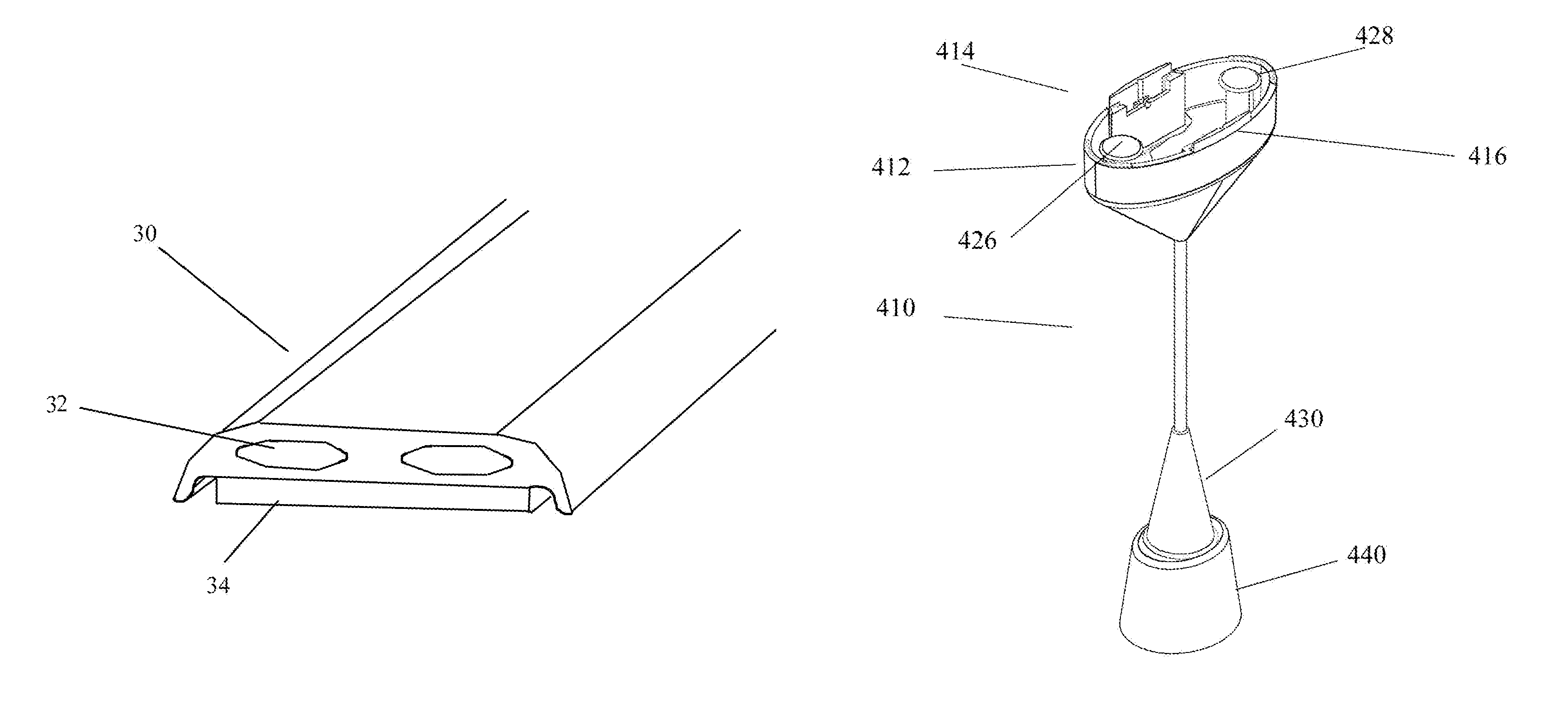
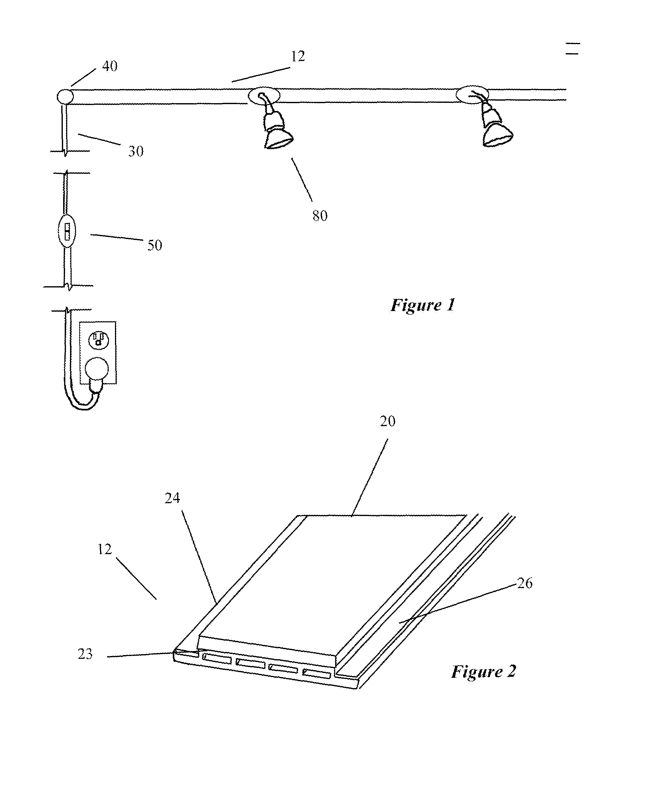
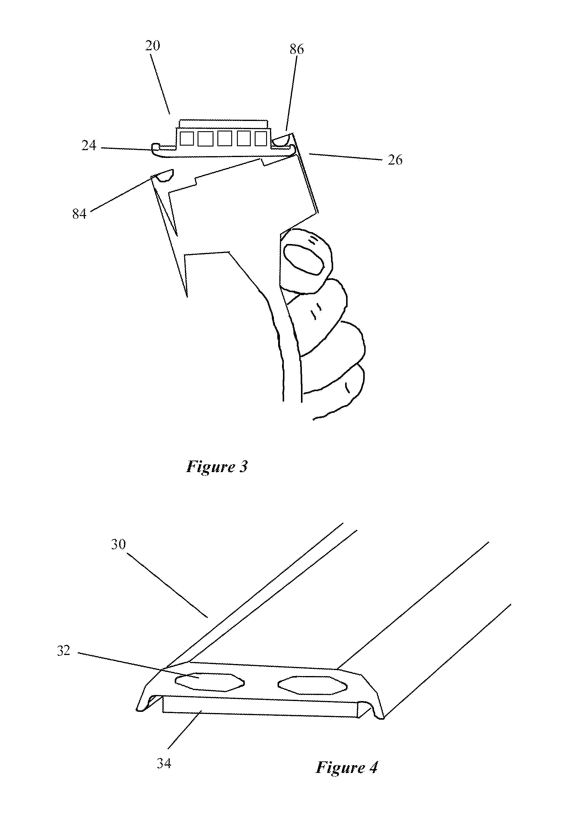
[0052]Several preferred embodiment of the present invention are illustrated in FIGS. 1–22. The electrical track lighting system 10 of a preferred embodiment shown in FIG. 1 includes a bendable track 12 having an adhesive backing, connection clip 40, a power supply 50, and fixtures 80. The system 10 is low profile, that is, the track mounts...


PUM


Abstract

An electrical track lighting system. The track lighting system includes a bendable track that includes a foamed adhesive strip on the upper surface separating two conductor rails. The track is cut to length and secured to the desired surface by the adhesive strip. Light fixtures having spring clip members with electrical contact surfaces engage onto the upper surface conductor rails of the track. Low voltage power is supplied to the track from an adhesive mounted transformer / dimmer switch through an adhesive backed power strip with adjustable angle snap connector.

Description

RELATED APPLICATIONS[0001]This application relates to provisional patent application 60 / 222,278 filed on Jul. 31, 2000. This application is a continuation-in-part of application Ser. No. 09 / 920,569, filed on Jul. 31, 2001 now U.S. Pat. No. 6,540,372.FIELD OF THE INVENTION[0002]This invention relates to the field of track lighting systems.BACKGROUND OF THE INVENTION[0003]Track lighting systems are well-known for use in interior decorating, display cases, and many other uses. Typical track lighting systems use a track having an interior channel with electrical conductors within the interior channel. Light fixtures usually include two tangs that are inserted into the track interior channel and twisted until contact is made with the electrical conductors. The tracks are normally mounted to a wall or ceiling by mounting screws or hung by a pendant.[0004]These systems are relatively difficult to install. It is necessary to cut the tracks to length with a saw or other tools and install wit...

Claims


Application Information

Patent Timeline
IPC IPC(8): H01R33/00F21V17/10F21V21/35
CPCB82Y15/00F21V17/101F21V21/35
Inventor JOSEPH, MARKSIMPSON, JANSON
Owner LITESNOW
Why Eureka
Try Eureka