Surface lighting device with closed oblique reflector

a surface lighting and reflector technology, applied in lighting and heating equipment, instruments, mechanical equipment, etc., can solve the problems of increasing costs, increasing costs, and affecting the uniformity of surface lighting devices, so as to improve the utilization of light beams and enhance uniform illumination and brightness.

Inactive Publication Date: 2006-11-14
HON HAI PRECISION IND CO LTD
View PDF11 Cites 15 Cited by
  • Summary
  • Abstract
  • Description
  • Claims
  • Application Information

AI Technical Summary

Benefits of technology

[0009]Another object of the present invention is to provide a surface lighting device capable of improving utilization of light beams emitted from an LED thereof.
[0010]A further object of the present invention is to provide a surface lighting device which provides enhanced uniform illumination and brightness.

Problems solved by technology

In general, it is more difficult to obtain uniform illumination when using a point light source compared with using a linear source, due to the divergent angles of light emitted from the point light source.
However, in the above-described configuration, one stick light guide body 16 needs two LEDs cooperating therewith, which increases costs.
It is therefore relatively difficult for the surface lighting device to produce uniform emitting light.

Method used


Image

  • Surface lighting device with closed oblique reflector
  • Surface lighting device with closed oblique reflector
  • Surface lighting device with closed oblique reflector

Examples


Embodiment Construction

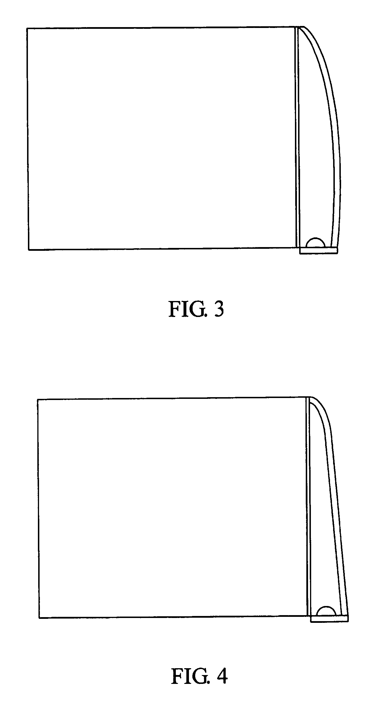
[0019]Referring to FIGS. 1–2, a first surface lighting device 1 in accordance with the present invention is used to illuminate a liquid crystal display panel. The surface lighting device 1 comprises a light guide plate 11, a brightness enhancement film 12, a light reflector 13, and an LED 14 for providing light beams.

[0020]The light guide plate 11 is a rectangular slab of transparent material such as acrylic resin, polycarbonate resin, polyvinyl chloride, or glass. The light guide plate 11 comprises a light incident surface 111, a light output surface (not labeled) adjoining the light incident surface 111, and a bottom surface (not labeled) opposite to the light output surface. The light output surface and / or the bottom surface of the light guide plate 11 can be formed with a dot-pattern of light diffusers (not shown) or with V-cut grooves (not shown), for scattering incident light and improving a brightness and uniformity of the light guide plate 11.

[0021]The brightness enhancement...


PUM


Abstract

A surface lighting device (1) includes a light guide plate (11), a point light source (14), and a light reflector (13) substantially juxtaposed with the light guide plate. The light guide plate has a light incident surface (111). The point light source is located between one end of the light reflector and the light incident surface. The light reflector comprises a reflecting portion (131) obliquely opposite to the light incident surface. The reflecting portion is adapted to receive light beams emitted from the point light source, and reflect the received light into the light incident surface of the light guide plate.

Description

BACKGROUND OF THE INVENTION[0001]1. Field of the Invention[0002]The present invention relates to a surface lighting device, and particularly to a surface lighting device for a liquid crystal display (LCD) or similar apparatus.[0003]2. The Related Art[0004]A typical LCD device comprises a liquid crystal display panel, and a surface lighting device mounted under the liquid crystal display panel for supplying light beams thereto. The surface lighting device mainly comprises one or more light sources for emitting light beams, and a light guide plate. The light guide plate receives the emitted light beams via a light incident surface thereof, and emits the light beams via a light output surface thereof in order to uniformly illuminate the liquid crystal display panel.[0005]Conventionally, there are two types of light sources used in a surface light device of an LCD: a linear source such as a cold cathode fluorescent lamp (CCFL), and a point light source such as a light emitting diode (LE...

Claims


Application Information

Patent Timeline
IPC IPC(8): F21V7/04F21V8/00G02B6/00
CPCG02B6/0028G02B6/0038G02B6/0046G02B6/0053
Inventor SUNG, CHANG-CHIEH
Owner HON HAI PRECISION IND CO LTD
Why Eureka
Try Eureka