
Disk drive with read while write capability

a technology of disk drives and read-write capabilities, applied in the field of disk drives, can solve the problems of limiting performance, consuming a lot of time, and complex and expensive servo writers

Inactive Publication Date: 2006-11-07
MAXTOR
View PDF40 Cites 42 Cited by
  • Summary
  • Abstract
  • Description
  • Claims
  • Application Information

AI Technical Summary

Benefits of technology

[0015]The present invention also provides disk drive self-servo writing by transferring a reference pattern to a reference disk. The reference pattern includes (1) a servo clock that provides transducer head circumferential relative position information, and (2) servo position information that provides transducer head radial relative position information. The reference disk and one or more data disks are installed into the disk drive. Then, during self-servo write, the reference pattern is read from the reference disk via a transducer head and the read servo clock and the servo position information are used to position and maintain one or more transducer heads at concentric tracks on one or more recording surfaces to simultaneously write servo patterns on the recording surfaces. Advantageously, rather than read the reference pattern from the reference disk via a transducer head sequentially followed by switching to other transducer heads to write the servo patterns on the data disks, as is conventional, the reference pattern is read via one transducer head to simultaneously clock out the servo patterns via the other transducer heads. Therefore, there is no need to switch-out the reference pattern to write the servo patterns.

Problems solved by technology

The disk drive has timing constraints which limit performance due to the read and write operations being mutually exclusive (not overlapping or simultaneous).
The servo writer is a complex and expensive machine typically stabilized on a large granite base to minimize unwanted vibration and employs laser interferometry for precise position measurements.
Further, servo writing by the servo writer is very time consuming.
Servo writing using servo writers in clean rooms requires both considerable capital investment and severe time penalties attributable to servo writer bottlenecks.
Further, as track densities increase with evolving disk drive designs, servo writers have to be replaced or upgraded at considerable capital expense.
However, disadvantages of this approach include (1) the self-servo write is time consuming, (2) repeatable run-out must be removed during the self-servo write, (3) the magnetic printing station is expensive, and (4) the reference disk has no absolute reference and since read and write operations are mutually exclusive, defects in the reference disk can exacerbate the problem.

Method used


Image

  • Disk drive with read while write capability
  • Disk drive with read while write capability
  • Disk drive with read while write capability

Examples


Embodiment Construction

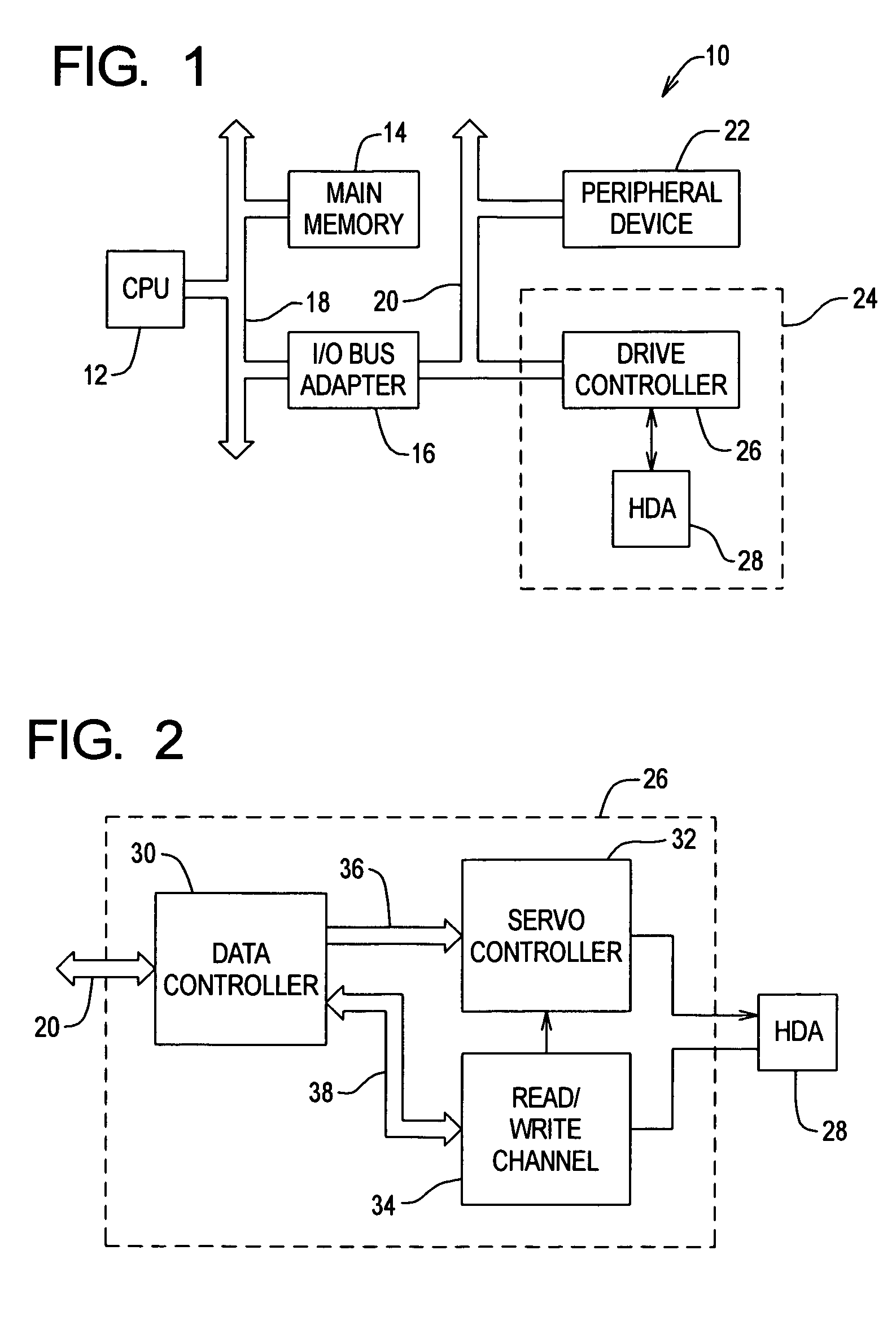
[0033]FIG. 1 shows a computer system 10 that includes a central processing unit (CPU) 12, a main memory 14, an I / O bus adapter 16, a system bus 18, an I / O bus 20, a peripheral device 22 and a disk drive 24. The CPU 12, the main memory 14 and the I / O bus adapter 16 are connected by the system bus 18, and the I / O bus adapter 16 is connected to the peripheral device 22 and the disk drive 24 by the I / O bus 20 (such as a SCSI bus). The disk drive 24 includes a drive controller 26 and a head disk assembly (HDA) 28.

[0034]FIG. 2 shows the drive controller 26 in more detail. The drive controller 26 includes a data controller 30, a servo controller 32, a read / write channel 34, a bus 36 and a data buffer bus 38. The data controller 30 is connected to the servo controller 32 by the bus 36, and the data controller 30 is connected to the channel 34 by the data buffer bus 38. The data controller 30 is also connected to the I / O bus 20, and the servo controller 32 and the channel 34 are connected to...


PUM

PropertyMeasurementUnit
distanceaaaaaaaaaa
frequencyaaaaaaaaaa
timeaaaaaaaaaa

Abstract

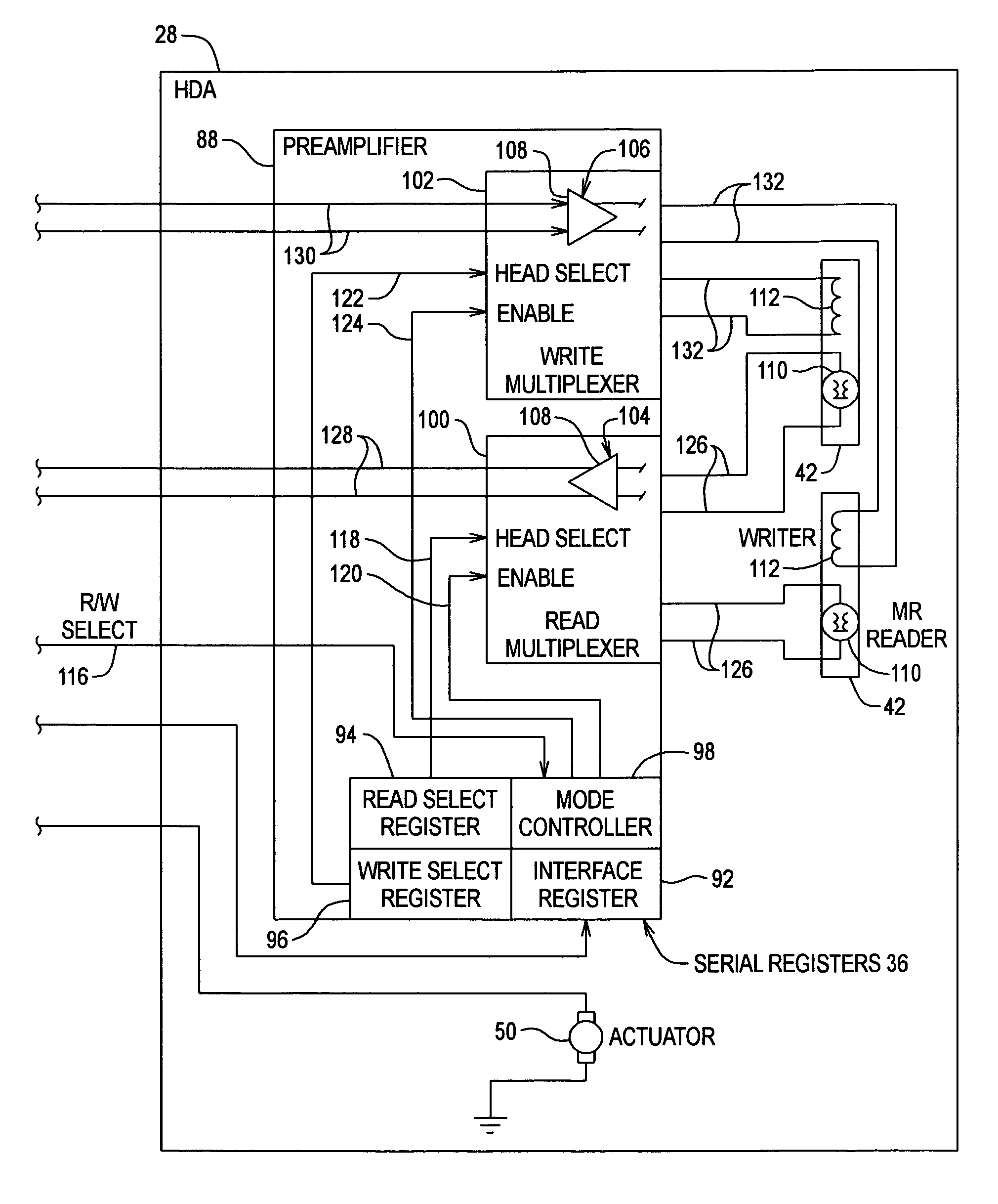
A disk drive includes recording media having one or more recording surfaces, one or more transducer heads positionable relative to the recording surfaces by an actuator operating within a head position servo loop, and a data transfer driver. A preamplifier in the data transfer driver includes one or more head interfaces, each head interface for controlling a transducer head for read and write operations, and a mode controller for controlling each head interface based on configuration information for selectively (i) reading data from at least one recording surface, (ii) writing data to at least one recording surface, and (iii) simultaneously reading data (such as a reference pattern) from at least one recording surface and writing data (such as servo patterns) to at least one recording surface.

Description

FIELD OF THE INVENTION[0001]The present invention relates generally to disk drives and in particular to preamplifiers for disk drives.BACKGROUND OF THE INVENTION[0002]Data storage devices such as disk drives are used for data storage and retrieval in a variety of applications. A disk drive includes a disk for storing information, a transducer (read / write) head for reading data from and writing data to the disk, a spindle motor for rotating the disk, a head carrier that supports the transducer head and an actuator for moving the head carrier and the transducer head. The disk drive may include multiple disks separated by spacer rings and stacked on a hub attached to the spindle motor, multiple transducer heads and multiple head carriers that each support at least one transducer head. The disk includes concentric tracks that each include servo sectors and interleaved data sectors. To access a data sector, the transducer head is moved radially across the tracks in a seek operation to th...

Claims


Application Information

Patent Timeline
Patent Type & Authority Patents(United States)
IPC IPC(8): G11B5/02
CPCB82Y10/00G11B5/59683G11B5/743G11B5/865G11B2005/0021
Inventor RAY, CHARLES D.LEE, GARYHURTADO, TONY
Owner MAXTOR
Learn More