
Light-triggered tattoo process

a tattoo and light-triggered technology, applied in the field of light-triggered tattooing process, can solve the problem of far more extensive use, and achieve the effect of high-quality tattooing patterns, rapid removal, and increased power density

Inactive Publication Date: 2006-11-07
TANG KENNETH Y +2
View PDF10 Cites 35 Cited by
  • Summary
  • Abstract
  • Description
  • Claims
  • Application Information

AI Technical Summary

Benefits of technology

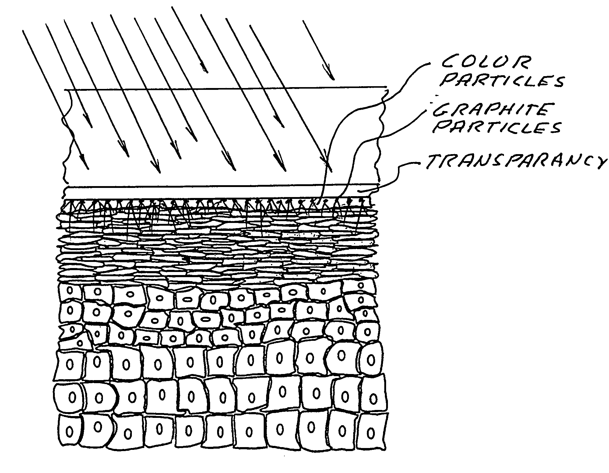
"The present invention provides a way to create tattoos using light energy. A strong absorber of light energy and tattoo material are sandwiched between a skin region and a transparent window. Short pulses of light illuminate the strong absorber creating micro-explosions that drive particles of the tattoo material into the skin region producing a tattoo. The process is safe, painless, and can create high-quality tattoos quickly and easily. The tattoos can be easily removed using the same laser."

Problems solved by technology

However, since the present process is so quick, so simple, so safe, so painless and temporary, Applicants believe that its use will be far more extensive than conventional tattoo processes.

Method used


Image

  • Light-triggered tattoo process
  • Light-triggered tattoo process
  • Light-triggered tattoo process

Examples


first embodiment

n

[0027]A first preferred embodiment of the present invention can be described by reference to FIGS. 2 through 8.

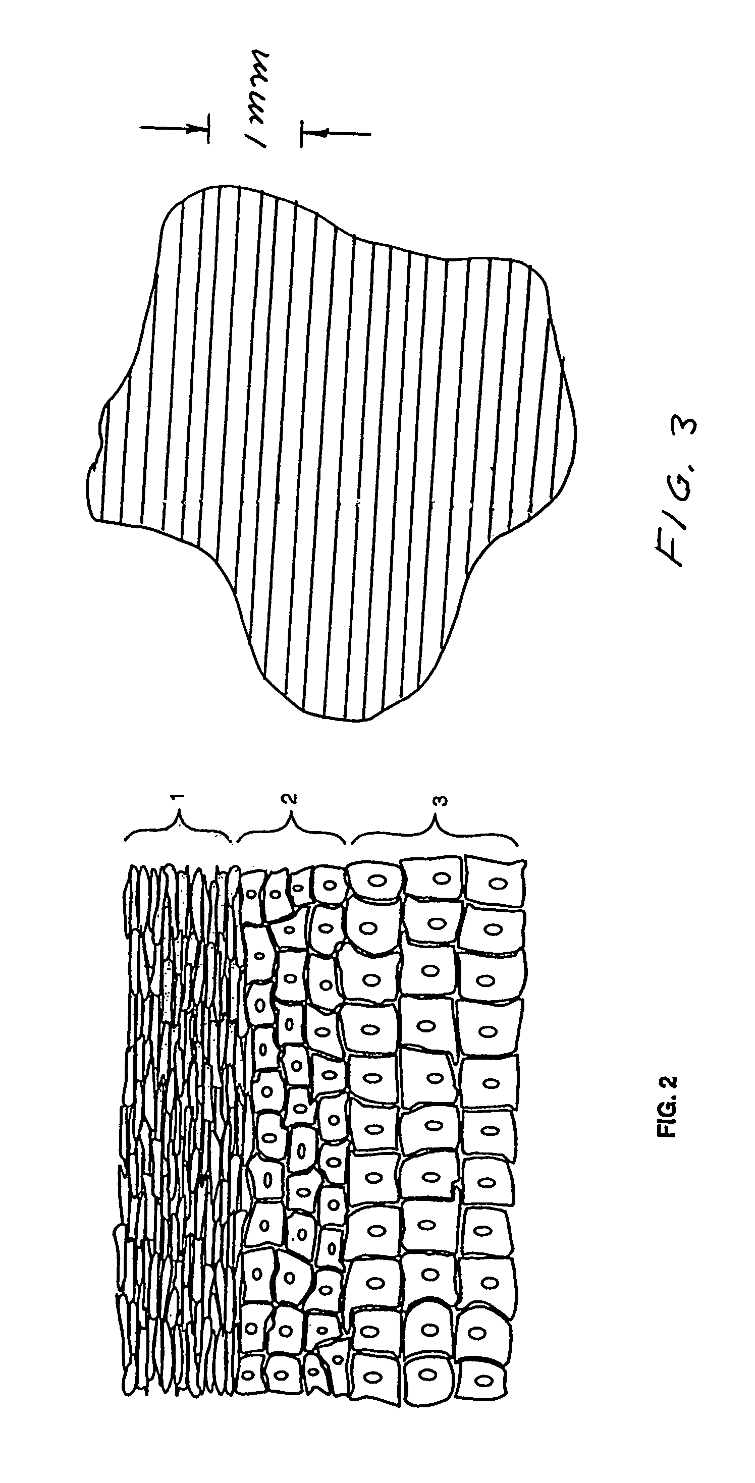
[0028]FIG. 2 shows layers of the epidermis as discussed in the Background section. The epidermis is typically a few hundred microns thick. The purpose of the present invention is to deposit beautiful color patterns in the epidermis region of the skin quickly and painlessly using lasers to produce micro explosions to drive the tattoo ink into this region of the skin.

[0029]In this embodiment a color printer / copier is used to prepare a color tattoo pattern. FIG. 3 shows how black ink (comprised of graphite particles) is applied to a transparency (such as Xerox laser / copier transparencies, Model 3R3108) by a modern color printer to produce a gray color. In a modern color printer / copier such as the Xerox Docucolor 12, colors are laid down in rows as shown in FIG. 3. Applicants count 5 rows per millimeter, so that the rows are on 200 micron centers. Dark to light control is prod...

second embodiment

[0030]A second technique for producing black tattoo patterns is shown with FIGS. 8 through 10. In this embodiment, relatively thick black lines are printed on transparencies using the same equipment as described above. The normal settings of the printer / copier provide adequate results. The cross section of a single line, such as the cross section of an “I” that is about 1 mm wide and maybe 50 graphite particle high is shown in FIG. 8. The tattoo could be a short phrase such as “NANCY MY LOVE” or a black outline pattern. The mirror image of the letters should be printed on the transparency. FIG. 9A shows the illumination step that is the same as above. In this case some of the graphite particles explode driving other particle into the skin. Excellent tattoos were produced with particles driven about 150 microns into the skin.

Explosive Graphite

[0031]Graphite is very absorptive of laser energy at the 1.06 micron wavelength. The latent heat of vaporization is about 105 J / cm3 for cold so...


PUM


Abstract

A light-triggered tattoo process. A strong absorber of light energy and tattoo material are sandwiched under pressure between a skin region and a transparent window. Short pulses of light, at frequencies strongly absorbed by the strong absorber, illuminates the strong absorber through the window creating micro-explosions in the strong absorber that drive particles of the tattoo material into the skin region producing a tattoo.

Description

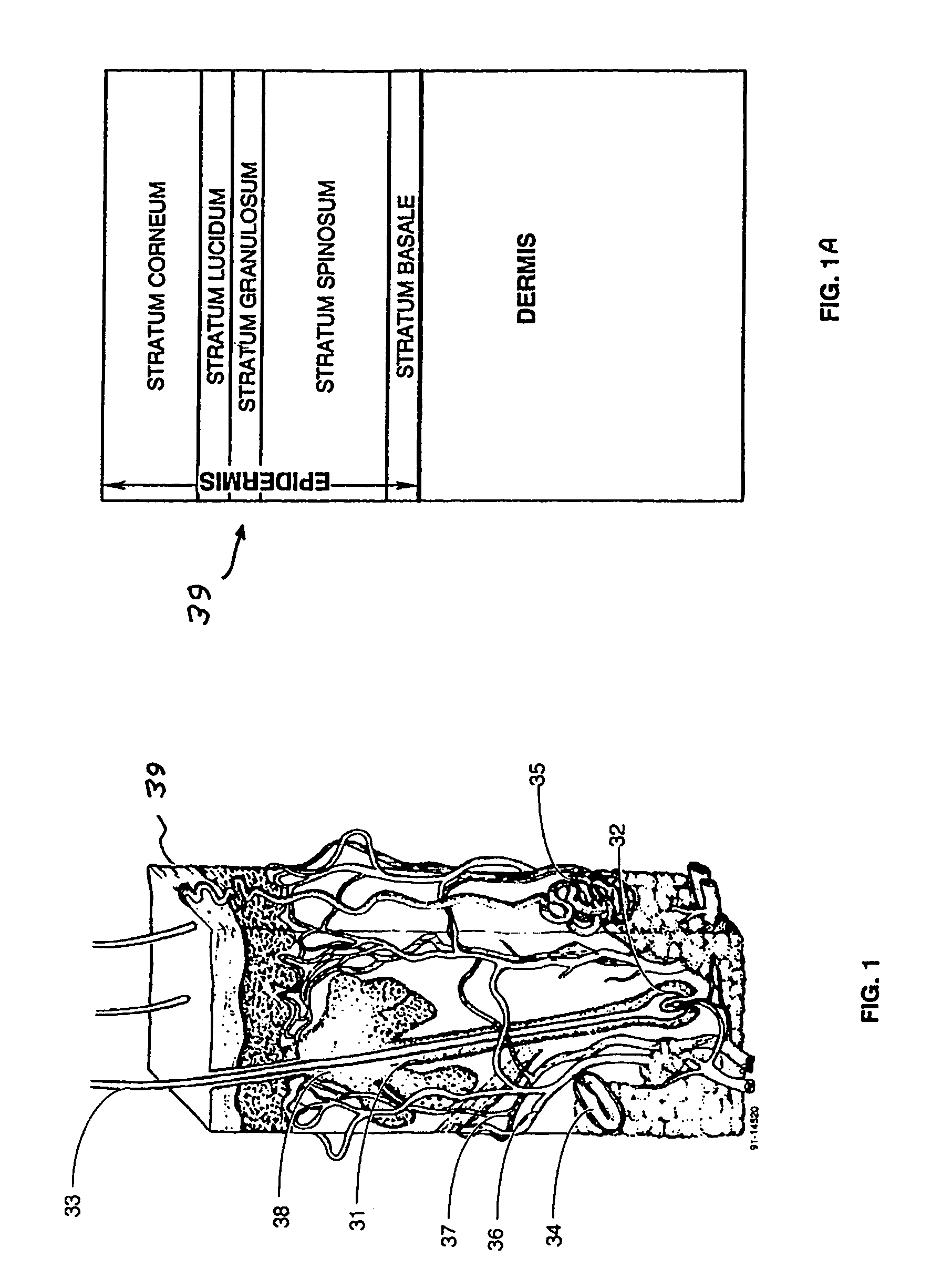
BACKGROUND OF THE INVENTION[0001]Humans have been applying tattoos to the skin for over 8000 years. The inks and dyes used were historically derived from substances found in nature and comprise a heterogeneous suspension of pigmented particles and other impurities. A well-known example is India ink, a suspension of carbon particles in a liquid.[0002]Tattoos are typically produced by applying, with tattoo needles, tattoo ink into the dermis, where the ink remains permanently. This technique introduces the pigment suspension through the skin by an alternating pressure-suction action caused by the elasticity of the skin in combination with the up-and-down movement of the tattoo needles. Water and / or other carriers for the pigment introduced into the skin diffuse through the tissues and are absorbed. The insoluble pigment particles remain in the dermis where they were initially placed, for the most part. Inks used for tattooing resist elimination by virtue of their inertness and the rel...

Claims


Application Information

Patent Timeline
Patent Type & Authority Patents(United States)
IPC IPC(8): A61B19/00A61B18/18A61B18/20
CPCA61B18/203A61B2018/00452
Inventor TANG, KENNETH Y.HUNTER, II, ALLEN M.TANG, BETTY W.
Owner TANG KENNETH Y
Learn More