
Construction machine

a construction machine and construction technology, applied in machines/engines, combustion air/fuel air treatment, transportation and packaging, etc., can solve the problems of reducing cooling efficiency, noise problem to at least the residents living at the higher floors, and inability to prevent upward leakage of noise, so as to reduce noise, increase the cooling effect, and reduce the load of the cooling fan

Active Publication Date: 2006-11-07
KOBELCO CONSTR MASCH CO LTD
View PDF10 Cites 29 Cited by
  • Summary
  • Abstract
  • Description
  • Claims
  • Application Information

AI Technical Summary

Benefits of technology

This design enhances cooling efficiency and reduces noise levels by 3 dB while maintaining smooth airflow, addressing the noise leakage and cooling efficiency challenges of existing systems.

Problems solved by technology

Noise cannot be prevented from leaking upward along with the exhaust gas discharged via the exhaust opening.
In an environment having high-rise apartment buildings near construction sites, in particular, the noise leaking upward from the hydraulic excavator causes noise problem to at least the residents living at higher floors.
In providing a soundproof design on the basis of exhaust gas flow, when the flow of air current from a cooling fan is made complicated, flow path resistance is increased, thereby reducing cooling efficiency.
In such a soundproof structure, however, since the flow of the cooling air current is guided to the duct path while changing the flow of the cooling air current in a complicated manner in the machine body, the flow path resistance increases, thereby increasing the load of the cooling fan.
In addition, since the duct path is formed at the counterweight, the space in the hood is reduced, thereby reducing the design freedom when disposing, for example, the engine.

Method used


Image

  • Construction machine
  • Construction machine
  • Construction machine

Examples


Embodiment Construction

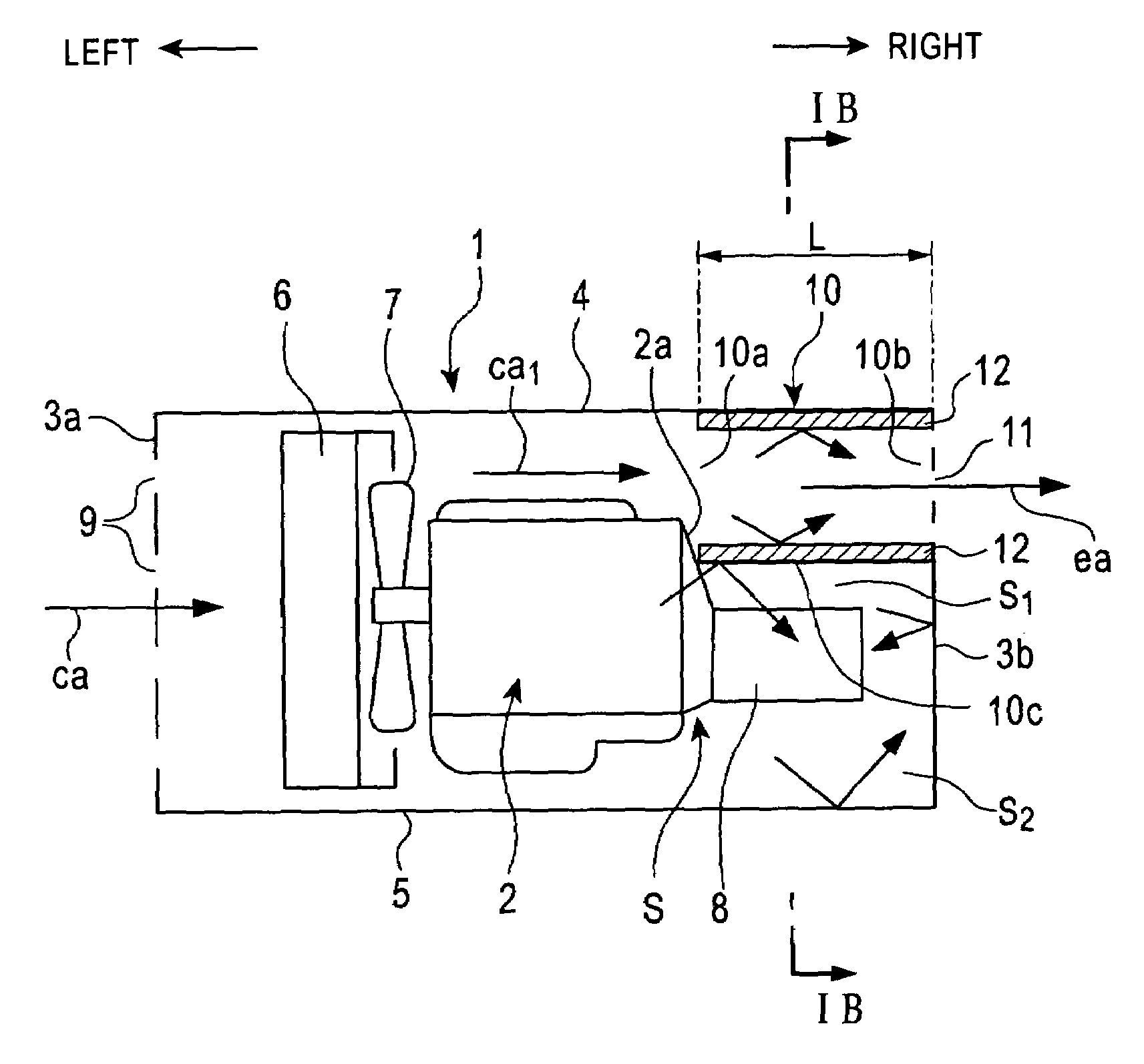
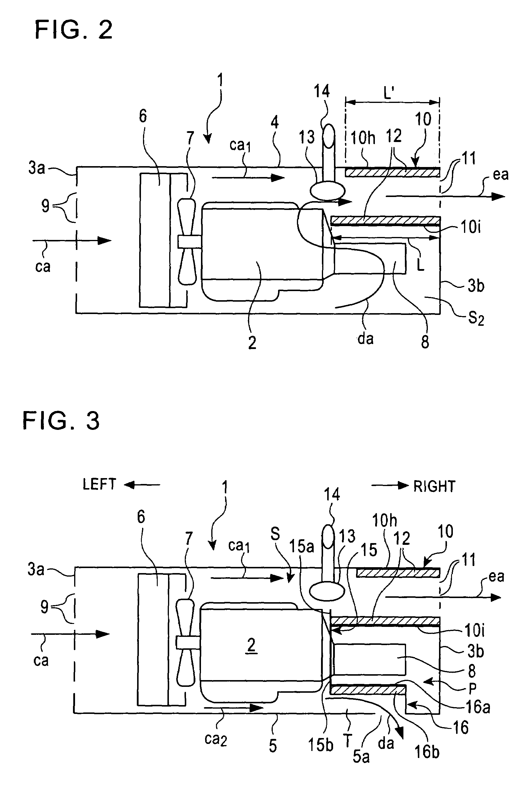
[0032]Hereunder, referring to FIGS. 1 to 16, embodiments of the present invention will be described in detail taking as an example the case in which an exhaust structure for discharging an exhaust gas in accordance with the present invention is applied to an upper rotating body of a hydraulic excavator which is one type of construction machine.

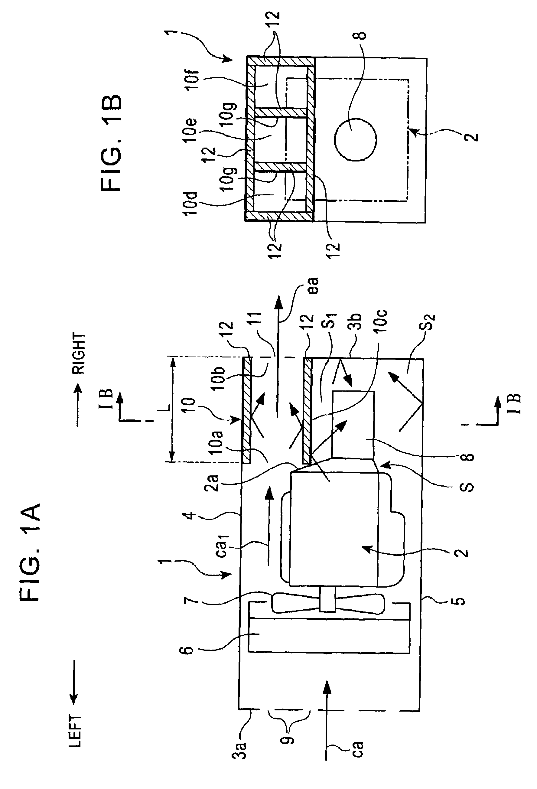
[0033]FIGS. 1A and 1B show the basic structure of an exhaust structure of a construction machine in accordance with the present invention. More specifically, FIG. 1A is a sectional view of an engine guard of a hydraulic excavator in a widthwise direction of the hydraulic excavator, and FIG. 1B is a sectional view taken along arrows IB shown in FIG. 1A.

[0034]The hydraulic excavator in accordance with the embodiment is assumed as having its engine disposed in the widthwise direction (that is, in a rightward / leftward direction in FIG. 1A) of the hydraulic excavator.

[0035]An engine guard 1 comprises a left side cover 3a, a right side cover 3b, an ...


PUM


Abstract

A construction machine includes an engine guard, an engine, a cooling fan, and a device for being cooled by the cooling fan, and an exhaust duct. The engine guard accommodates the engine and has intake and exhaust openings. The intake opening and the exhaust opening are disposed in different side covers. The side covers correspond to the left and right side walls of the engine guard. The engine, the cooling fan, and the device are accommodated in the engine guard. The exhaust duct is disposed above and behind the engine, parallel with the flow of a fan air which has been used for cooling the engine, and substantially horizontally. The exhaust duct has an exit connected to the exhaust opening. The fan air introduced from the intake opening flows substantially linearly along the cooling fan, the engine, and the exhaust duct and is discharged from the exhaust opening.

Description

BACKGROUND OF THE INVENTION[0001]1. Field of the Invention[0002]The present invention relates to a construction machine, such as a hydraulic excavator, having an exhaust gas discharging structure.[0003]2. Description of the Related Art[0004]Ordinarily, a hydraulic excavator comprises an engine guard which covers, for example, an engine and a cooling fan, and has an exhaust opening or an opening for an exhaust gas in the top surface thereof for discharging exhaust gas. Noise cannot be prevented from leaking upward along with the exhaust gas discharged via the exhaust opening.[0005]In an environment having high-rise apartment buildings near construction sites, in particular, the noise leaking upward from the hydraulic excavator causes noise problem to at least the residents living at higher floors.[0006]The noise level of a hydraulic excavator is calculated by measuring sound pressure levels with a plurality of microphones disposed on an imaginary hemisphere face (parallelepiped face)...

Claims


Application Information

Patent Timeline
Patent Type & Authority Patents(United States)
IPC IPC(8): F02B77/04F02B77/13E02F9/00B60K11/08B60K13/04B60R13/08E02F9/08F01P5/06
CPCB60R13/0838B60R13/0861B60R13/0876E02F9/0866
Inventor KIMURA, YASUMASANAKASHIMA, HAJIMEUEDA, KAZUHIRO
Owner KOBELCO CONSTR MASCH CO LTD
Learn More