
Hinged clip with separable jaws

a technology of separable jaws and hinges, which is applied in the field of hinges, can solve the problems of affecting the quality of the clip, the inability to adapt to the shape of the hinge, and the inability to mold the clip as a unitary structure,

Inactive Publication Date: 2006-11-07
FOLKMAR JAN
View PDF10 Cites 19 Cited by
  • Summary
  • Abstract
  • Description
  • Claims
  • Application Information

AI Technical Summary

Benefits of technology

[0013]The disposition of the hinge structure rearwardly of the mutually confronting jaw surfaces permits a clip to be formed with separately formed jaws which has a closure capacity which is generally not less than that of a comparably sized clip having a living hinge. It also permits a hinge geometry which is relatively independent of the jaw structure.
[0015]Where the upper jaw of the clip is provided with a channel therealong within which a rib formed on the lower jaw may be interleaved, the rearward end of the channel may be closed by a rear wall to increase the strength of the jaw. Suitably, a portal may be formed in the rear wall to communicate with the passage to permit the rearwardly projecting tab to pass therethrough.

Problems solved by technology

However, such form of hinge is not always suitable, for example where it is desired to form the clip from a material with a relatively high modulus of elasticity.
Also, it is not always convenient or desired that the clip be molded as a unitary structure.
Accordingly, the channeled jaw may be highly stressed when the clip is in use, leading to a possible failure of the clip.
Moreover, while it is not uncommon that one at least of the jaws of a clip be formed with the requisite channel structure, this is not necessarily the case.
This may result in the failure of the latch elements to engage together, and where the hinge is of a snap together type, in the disengagement of the hinge elements.

Method used


Image

  • Hinged clip with separable jaws
  • Hinged clip with separable jaws
  • Hinged clip with separable jaws

Examples


second embodiment

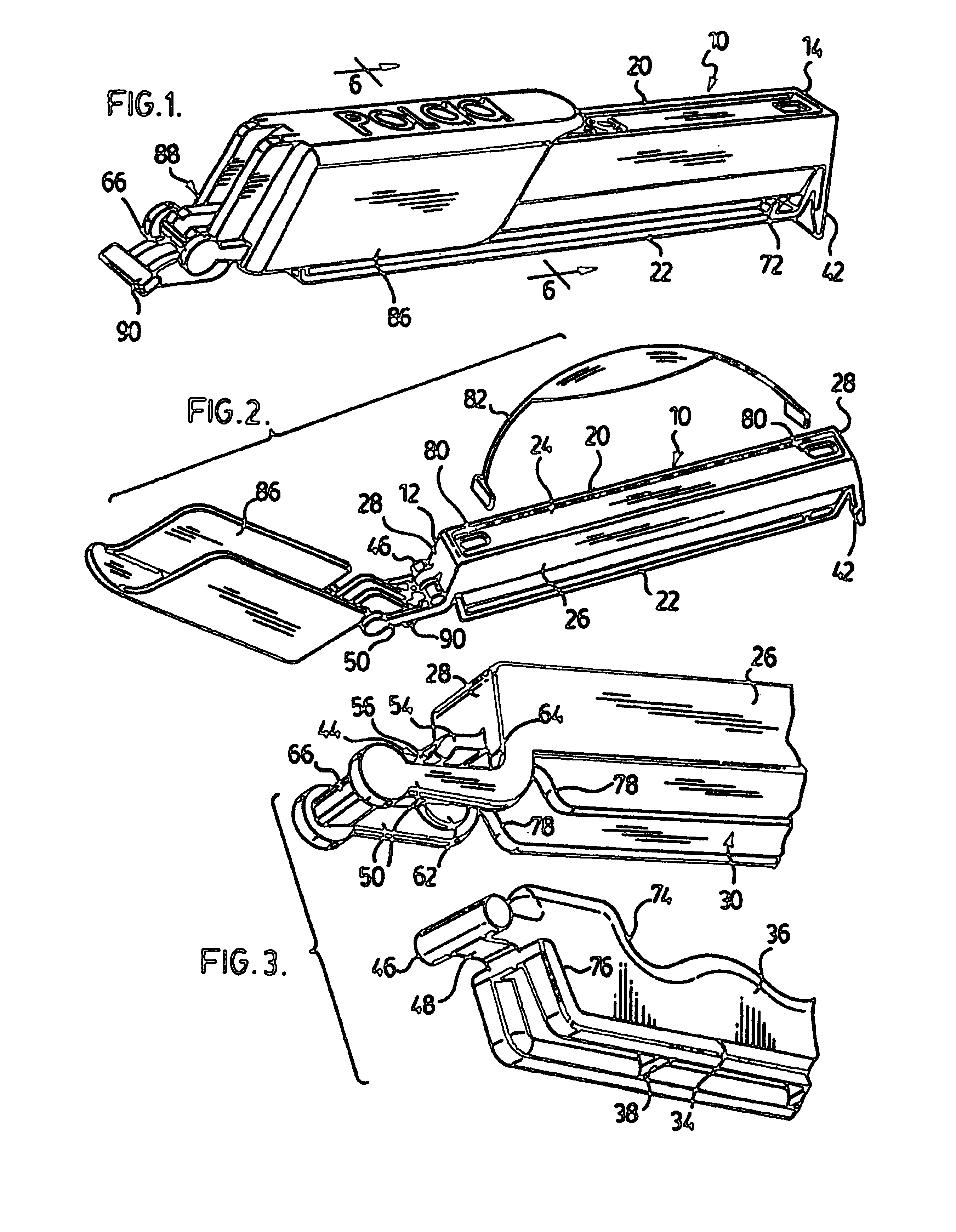
[0027]FIG. 8 shows a clip in accordance with a second embodiment in perspective, exploded view from the rear, right side;

third embodiment

[0028]FIG. 9 shows a clip in accordance with a third embodiment in perspective, exploded view from the rear, left side; and

[0029]FIG. 10 shows the clip of FIG. 9 in one manner of use.

DESCRIPTION OF THE PREFERRED EMBODIMENTS

first embodiment

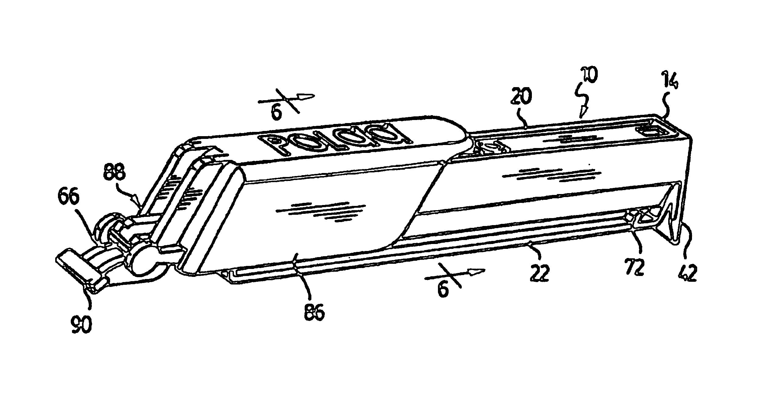
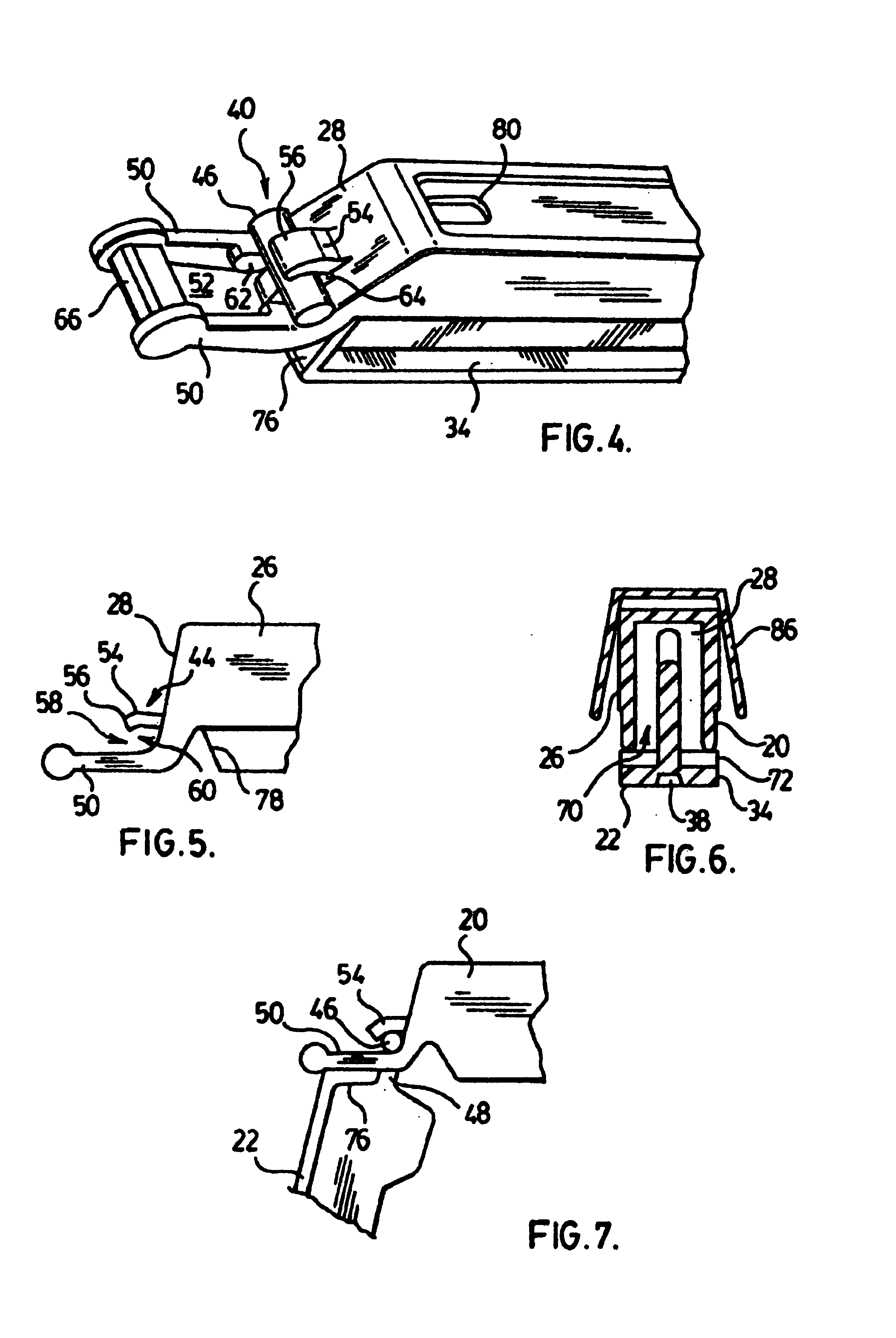
[0030]Referring to the drawings in detail, in accordance with the invention illustrated in FIGS. 1-7, a heavy duty clip is identified generally therein by the numeral 10. Clip 10 has a rearward end 12 and a forward end 14, and a longitudinal axis therebetween, and in general will have an axial plane of symmetry. Clip 10 comprises an upper jaw 20 and a lower jaw 22; the upper jaw is defined in part by a top wall 24, side walls 26, and end walls 28, each of which depend from the top wall, with the end walls interconnecting the side walls, the walls together forming a downwardly open channel 30.

[0031]Lower jaw 22 comprises an axially extending flange 34 and an axially extending rib 36 upstanding from the flange. Given that clip 10 of this first embodiment is particularly intended for heavy duty use, the cross section of the flange at the juncture with rib 36 may be physically large, and in accordance with general molding practice, the mass of the cross section is reduced by forming fla...


PUM


Abstract

A molded clip for closing bags and the like includes a pair of claws with a latch and a hinge at opposed ends. The hinge extends rearwardly from the jaws and includes a hinge bearing with a rearwardly facing opening of restricted diameter thereto. The other jaw includes a fixed hinge pin which may be snap engaged into the bearing by resilient passage through the opening. Where the jaws are relatively large, they may be provided with cooperating shoulders that restrict axial movement of the jaws under reactively generated forces. In accordance with one embodiment, one of the jaws is double sided, and the clip may be assembled with either of these sides confronting the other jaw to provide different clip functions.

Description

FIELD OF INVENTION[0001]This invention relates to clips which have a use for closing bags, although they are not necessarily limited to such use.BACKGROUND OF THE INVENTION[0002]Clips of the foregoing nature are well known in commerce, and may be generally exemplified by the clips described in U.S. Pat. Nos. 4,887,335, and 6,058,572, of common inventorship herewith. The clips in general comprise a pair of axially extending jaws which are interconnected at one end by a hinge so as to be swingable between an open position and a closed position, in which confronting portions of the jaws are in proximity, and a latch at the axially opposed end for releasably retaining the jaws closed. For economy of manufacture the hinge is typically a live hinge (also known as a living hinge). However, such form of hinge is not always suitable, for example where it is desired to form the clip from a material with a relatively high modulus of elasticity. Also, it is not always convenient or desired that...

Claims


Application Information

Patent Timeline
Patent Type & Authority Patents(United States)
IPC IPC(8): B65D77/10B65D33/30B65D33/16B65D33/17F16B2/10
CPCB65D33/1675Y10T24/15Y10T24/44538
Inventor FOLKMAR, JAN
Owner FOLKMAR JAN
Learn More