
Storage system structure for storing relational cache metadata

a storage system and metadata technology, applied in the field of storage system caches, can solve the problems of requiring a large battery backup, unable to address the entire cache in the cpu memory space, and limited memory bandwidth

Active Publication Date: 2006-10-31
ORACLE INT CORP
View PDF11 Cites 84 Cited by
  • Summary
  • Abstract
  • Description
  • Claims
  • Application Information

AI Technical Summary

Problems solved by technology

For example, if the storage cache is placed in the CPU memory space, as the size of the storage cache increases, it may become impractical to address the entire cache in the CPU memory space.
In addition, there may be limited memory bandwidth.
Further, to place the storage cache in the CPU memory space may require a large part of the system memory to survive a power loss, thereby requiring a large battery backup.
If the storage cache is placed in the I / O space, data requests may be markedly slow due to such conditions as slower I / O buses compared to the CPU memory bus and constrained accessibility of the I / O buses, for example.
However, when the primary cache fails, there is a delay associated with reconstructing the metadata from the self-describing cache.
This reconstruction delay impacts the availability and performance of the system under failure conditions.
However, as more powerful metadata structures are employed, the metadata size may increase, thereby increasing the metadata overhead.
In addition, splitting the cache may increase the cache management burden by having to manage more than one type of cache with respect to allocation, population and de-staging, for example.
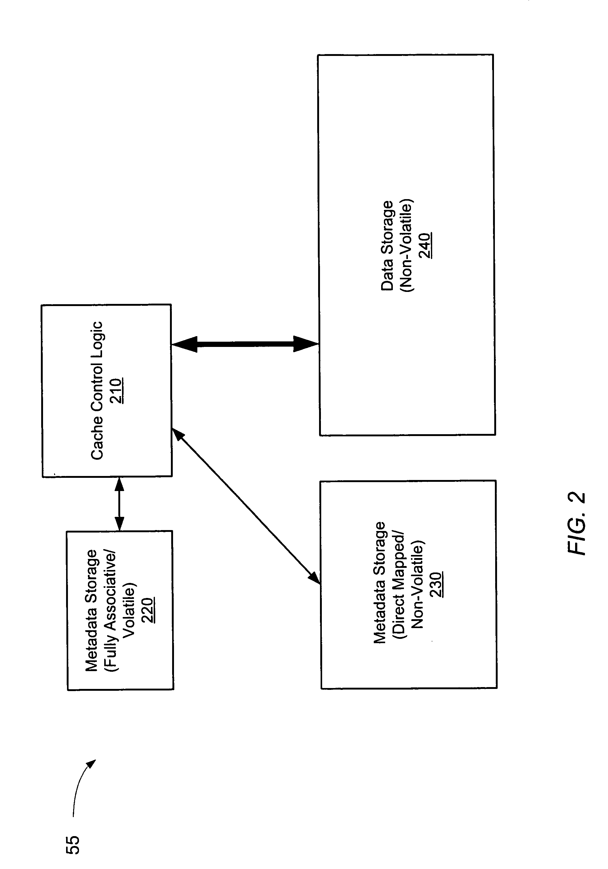
However, unlike the cache and the first metadata storage, in one implementation, the second metadata storage may be a volatile storage.

Method used


Image

  • Storage system structure for storing relational cache metadata
  • Storage system structure for storing relational cache metadata
  • Storage system structure for storing relational cache metadata

Examples


Embodiment Construction

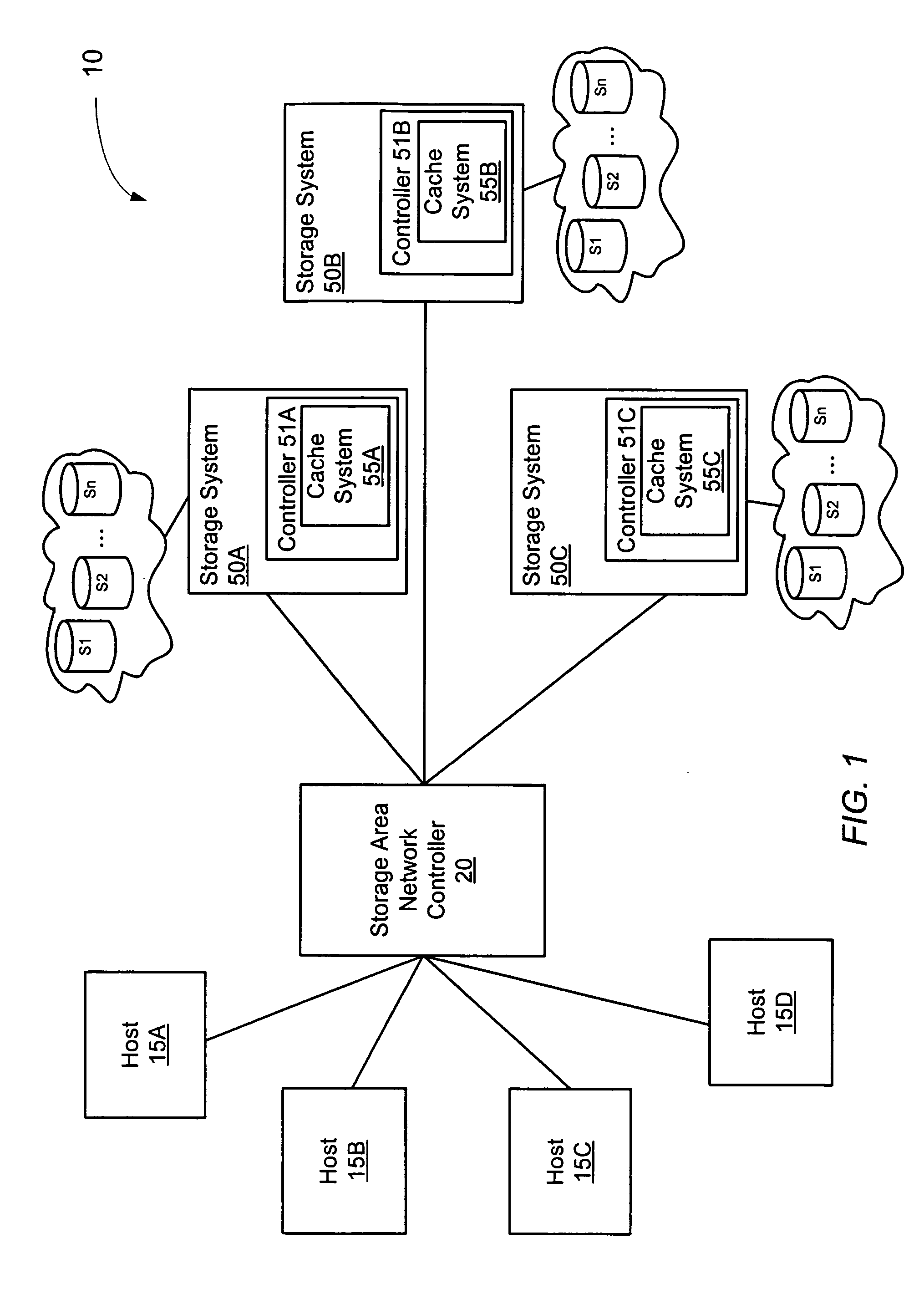
[0017]Turning now to FIG. 1, a block diagram of one embodiment of a computer system employing a plurality of storage systems is shown. Computer system 10 includes a plurality of hosts, 15A through 15D, that are coupled to a plurality of storage systems, designated 50A through 50C, via a storage area network (SAN) controller 20. The interconnections between hosts 15 and SAN controller 20 and between SAN controller 20 and storage systems 50 may be implemented using any type of high bandwidth protocol such as Fibre Channel or Gigabit Ethernet, for example. It is noted that components having a reference number followed by a letter may be referred to by the reference number alone when appropriate. It is further noted that computer system 10 is an exemplary system illustrative of only one of many different storage system topologies. For example, in other embodiments, computer system 10 may include any number of hosts 15 coupled to any number of storage systems 50. In addition, in some emb...


PUM


Abstract

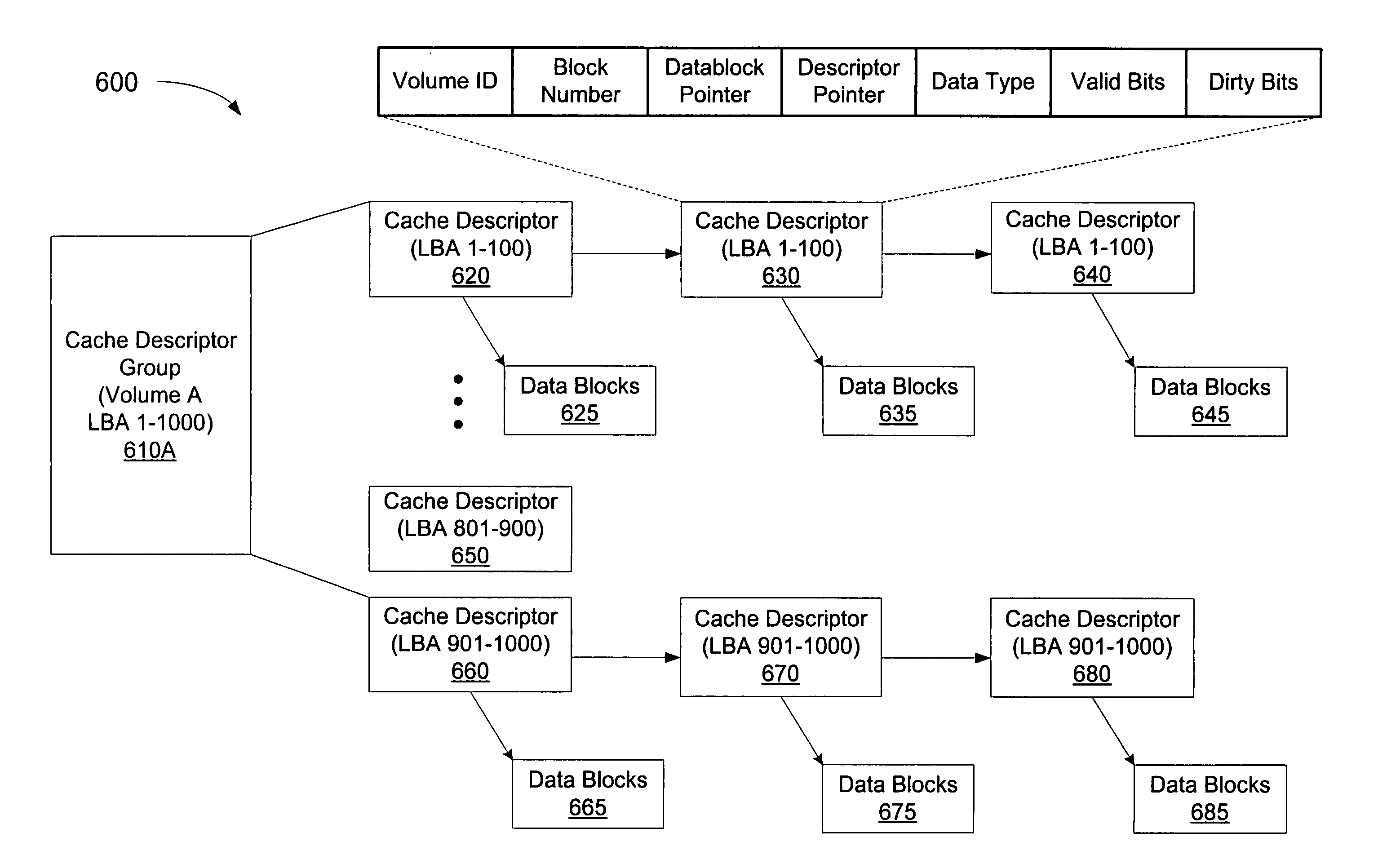
A storage system includes a cache and a collection of metadata, organized by their associations with regard to the data they represent. In one embodiment, the cache stores data blocks in a first plurality of locations. A first metadata storage stores metadata including block addresses of data blocks within the cache. A second metadata storage includes a second plurality of locations, each for storing metadata including a block address identifying a corresponding data block within the cache. The metadata stored within the second metadata storage also includes a first pointer to the corresponding data block. In addition, at least one of the second locations may store a second pointer to another of the second locations that stores metadata corresponding to a related data block. The cache and the first metadata storage are non-volatile storages; however, the second metadata storage may be a volatile storage.

Description

BACKGROUND OF THE INVENTION[0001]1. Field of the Invention[0002]This invention relates to storage system caches and, more particularly, to metadata design within the storage system cache.[0003]2. Description of the Related Art[0004]Many storage systems employ non-volatile caching as a means of improving input / output (I / O) performance between the storage subsystem and the host(s). In addition, the non-volatile cache may be used to improve internal storage system operations such as error logging, recovery, and reconstruction for example.[0005]Many such storage caches include data storage as well as metadata storage. Metadata typically includes information that describes the data. For example, metadata may include validity information and a pointer to the location of the data. Thus, at any point in time, the integrity of the metadata is critical. For systems having a high reliability, availability and serviceability (RAS) rating, in addition to the data, the metadata is generally store...

Claims


Application Information

Patent Timeline
Patent Type & Authority Patents(United States)
IPC IPC(8): G06F12/00G06F12/08
CPCG06F12/0866G06F12/0897G06F12/0893
Inventor RAO, RAGHAVENDRA J.
Owner ORACLE INT CORP
Learn More