
Radio frequency enabled control of environmental zones

a technology of environmental zones and radio frequency, applied in the direction of instruments, heating types, static/dynamic balance measurement, etc., can solve the problems of difficult heating or cooling of those rooms, occupants' dislike of the environmental control of different and the inability to control the environmental control of particular rooms or other areas of the residen

Active Publication Date: 2006-10-31
ADEMCO INC
View PDF33 Cites 91 Cited by
  • Summary
  • Abstract
  • Description
  • Claims
  • Application Information

AI Technical Summary

Benefits of technology

The present invention provides a system, apparatus, and method for controlling environmental conditions in a residence or building using radio frequency enabled environmental controllers. The system includes a zone controller that can control the environmental conditions in multiple zones. The controller receives commands from the zones, which include a unique identifier and an environmental control command. The controller uses a unidirectional wireless communication to transmit the commands to the zones. The system also includes binding switches for each zone that are activated when the unique identifier is associated with the command. The system can detect and address corruption of the commands, and can also include a visual indicator to indicate the binding operation is in progress. The technical effects of the invention include improved control of environmental conditions, improved efficiency, and improved user experience.

Problems solved by technology

While a single environmental control system may control an entire residence (or other facility), various portions of the residence may not be environmentally controlled to the liking of occupants of those portions of the residence.
As another example, some rooms may be physically located such that heating or cooling those rooms is more difficult.
In any of these types of situations, environmental control of particular rooms or other areas of a residence may prove to be difficult.
However, dividing homes or other facilities into zones and providing separate thermostats for each zone requires additional wiring.
This may be particularly burdensome in residences where a single-zone system is to be upgraded to a multi-zone system.
Invasive wiring of thermostats and zone control systems into existing walls and other structures can be expensive and inconvenient for the homeowner.

Method used


Image

  • Radio frequency enabled control of environmental zones
  • Radio frequency enabled control of environmental zones
  • Radio frequency enabled control of environmental zones

Examples


Embodiment Construction

[0027]In the following description of various exemplary embodiments, reference is made to the accompanying drawings which form a part hereof, and in which is shown by way of illustration various embodiments in which the invention may be practiced. It is to be understood that other embodiments may be utilized, as structural and operational changes may be made without departing from the scope of the present invention.

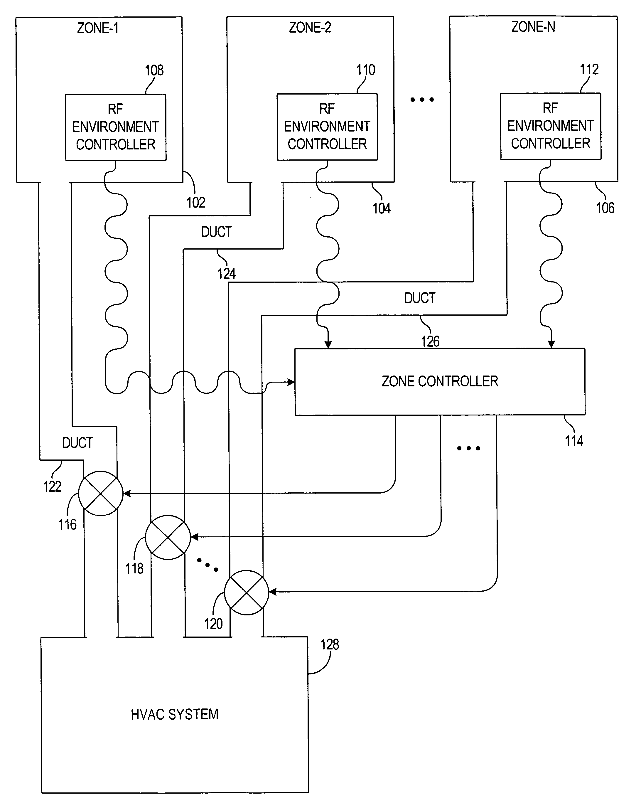
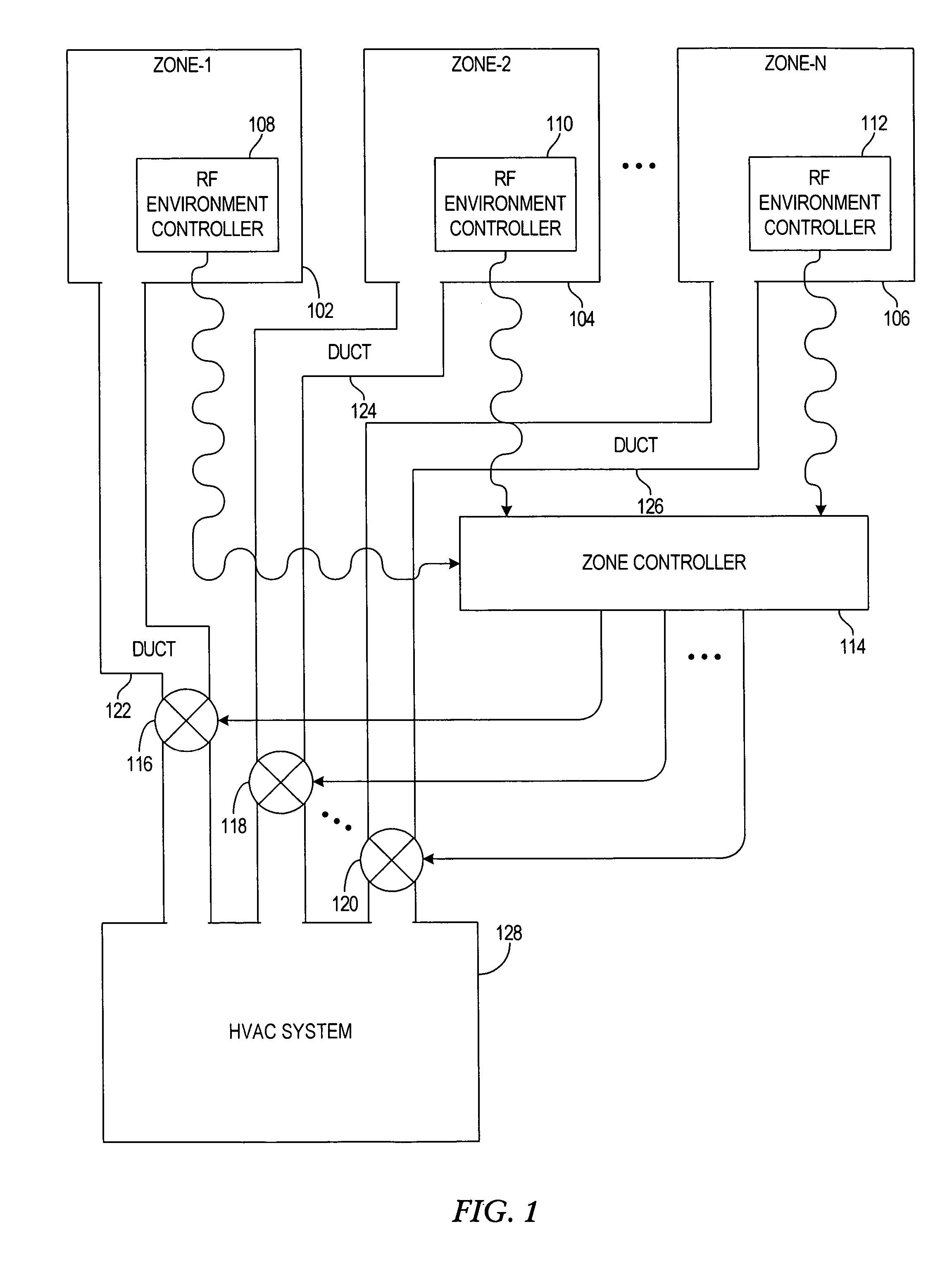
[0028]Generally, the present invention provides control of environmental zones in a residence or other building using radio frequency enabled environmental controllers. Environmental controllers such as thermostats are equipped with wireless transmitters. Commands issued from the thermostats include respective unique identifiers associated with its respective thermostat, where the unique identifier is used to bind the particular thermostat with a respective zone in a multi-zone environment. A zone controller capable of wirelessly receiving these commands controls HVAC equ...


PUM


Abstract

A system, apparatus and method for controlling environmental zones in a residence or other building using radio frequency enabled environmental controllers. At least one damper is associated with each of the various zones. From each environmental controller, a command is wirelessly transmitted, where the command includes an environmental control command and a respective unique identifier associated with the environmental controller. The command is received at a zone controller, and each environmental controller is bound with a respective one of the zones using the respective unique identifier associated with the environmental controller. The damper(s) associated with the zone that is bound with the environmental controller associated with the unique identifier from the command are operated in response to the zone controller. Environmental adjustment equipment is operated, which is responsive to the zone controller to execute the environmental control command.

Description

FIELD OF THE INVENTION[0001]This invention relates in general to environmental control systems, and more particularly to a system, apparatus and method for facilitating installation and enhancing flexibility of multi-zone environmental control systems.BACKGROUND OF THE INVENTION[0002]Commercial and residential environmental control systems generally involve controlling any one or more environmental characteristics such as temperature, humidity, air filtration, and the like. While a single environmental control system may control an entire residence (or other facility), various portions of the residence may not be environmentally controlled to the liking of occupants of those portions of the residence. For example, some rooms in a home may be a longer distance from a central heating, ventilation and air conditioning (HVAC) system, and are not cooled and / or heated as well relative to other rooms closer to the HVAC system. As another example, some rooms may be physically located such t...

Claims


Application Information

Patent Timeline
Patent Type & Authority Patents(United States)
IPC IPC(8): G05D23/00F24F3/00F24F11/00
CPCF24F11/006G05D23/1934F24F2011/0068F24F11/30F24F11/62F24F11/56
Inventor FISHER, JAMES L.
Owner ADEMCO INC
Learn More