Acoustic fluid machine
a technology of acoustic fluid and acoustic pump, which is applied in the field of acoustic pump, can solve the problems of increasing the difficult to occur malfunction, and large cost of manufacturing the actuator, and achieves the effect of reducing the load
- Summary
- Abstract
- Description
- Claims
- Application Information
AI Technical Summary
Benefits of technology
Problems solved by technology
Method used
Image
Examples
first embodiment
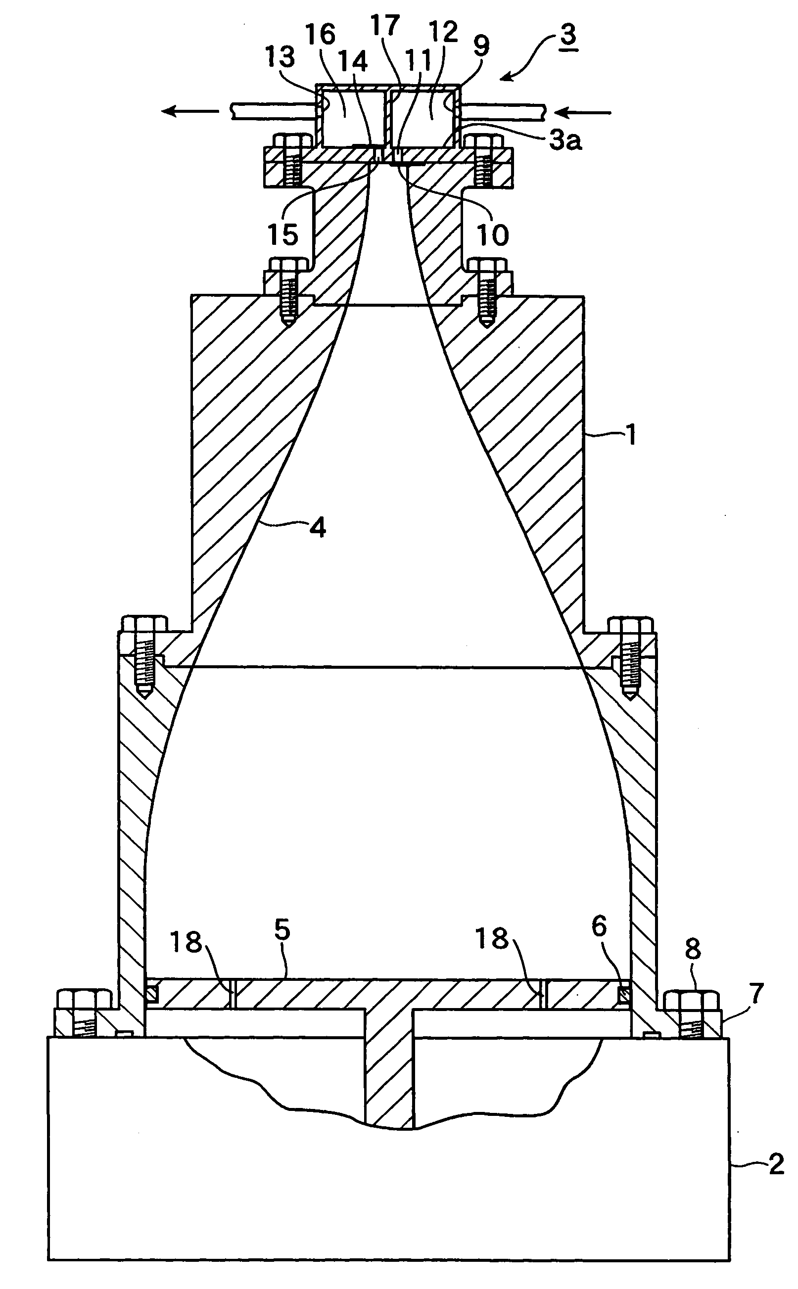
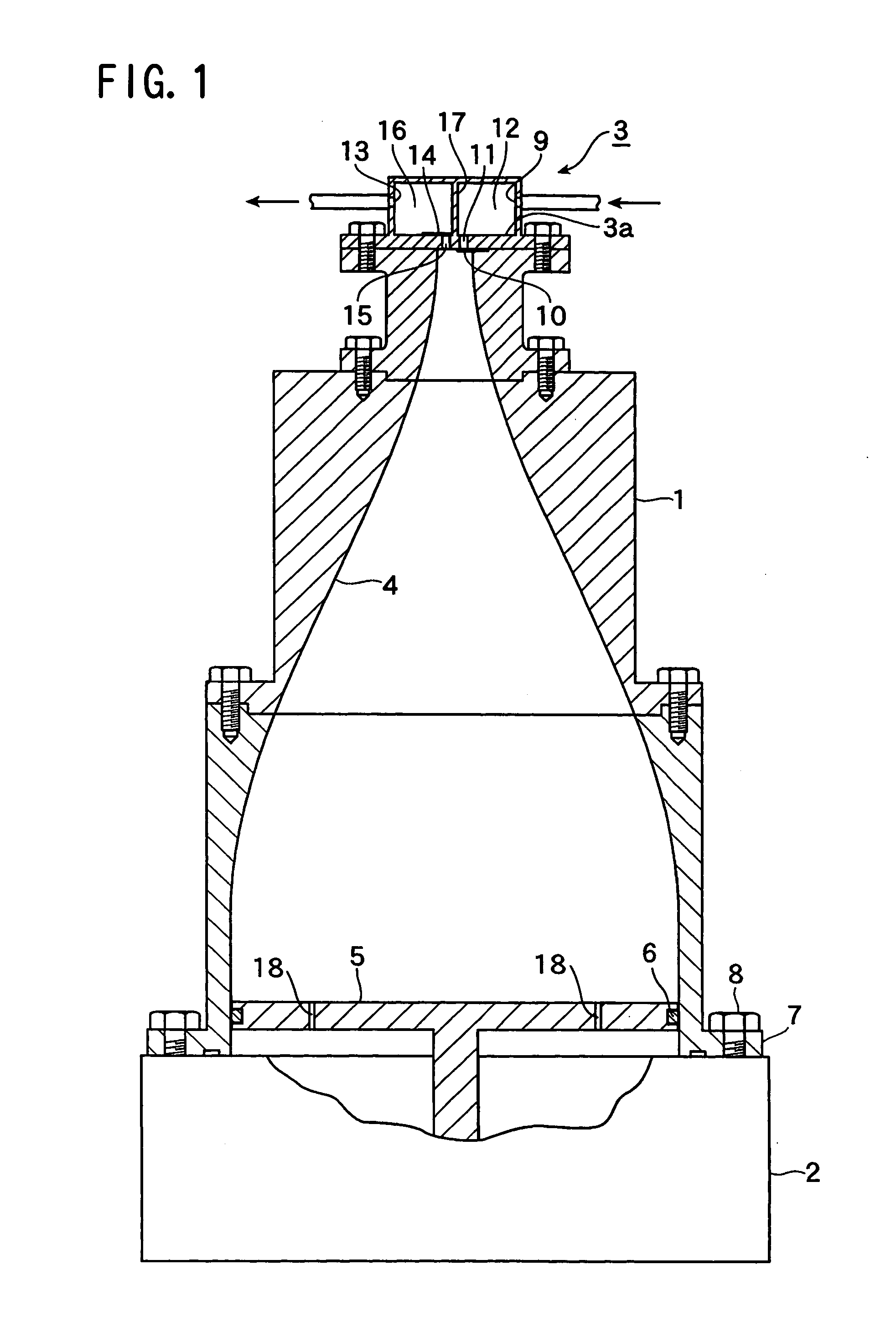
[0017]FIG. 1 shows a vertical sectional view of an acoustic fluid machine according to the present invention.
[0018]The acoustic fluid machine has an acoustic resonator 1, an actuator 2 at a larger-diameter base of the acoustic resonator 1, and a valve device 3 at the smaller-diameter upper end.
[0019]The acoustic resonator 1 has a resonant cavity 4 having the larger-diameter lower end and smaller-diameter upper end, and the resonant cavity 4 has an inner surface to comply with the following formula:
[0020]r(x)=rp-ro2cos(πLx)+rp+ro2
where L is the length of the resonant cavity, rp is the radius of the lower end or base of the actuator and ro is the radius of the upper end or sucking or discharging upper end.
[0021]The actuator 2 is also a support, and has a piston 5 reciprocated by the actuator 2. The piston 5 is made of light alloy and fitted in the lower end of the resonant cavity 4. A seal 6 is fitted in the outer circumference of the piston 5. The acoustic resonator 1 has an outw...
second embodiment
[0033]FIG. 2 is an enlarged vertical sectional view of the second embodiment according to the present invention, and FIG. 3 is a horizontal sectional view taken along the line III—III in FIG. 2. The basic structure is similar to that in FIG. 1, and only differences will be described.
[0034]A suitable number of grooves 19 are formed on the outer circumferential surface of a piston 5 and a seal 6 is provided on the inner surface of the acoustic resonator 1.
[0035]Through the grooves 19, front and rear spaces of the piston 5 communicate with each other, and the object of the invention can be achieved.
third embodiment
[0036]FIG. 4 is an enlarged vertical sectional front view of the present invention, and FIG. 5 is a horizontal sectional view taken along the line V—V in FIG. 4.
[0037]A recess 20 is formed on the outer circumferential surface of a piston 5, and a seal 6 is fitted in the inner circumferential surface of an acoustic resonator 1. Through the recess 5, front and rear spaces of the piston 5 communicate with each other, and the object of the invention can be achieved.
PUM
 Abstract
Description
Claims
Application Information
 - R&D
- Intellectual Property
- Life Sciences
- Materials
- Tech Scout
- Unparalleled Data Quality
- Higher Quality Content
- 60% Fewer Hallucinations
Browse by: Latest US Patents, China's latest patents, Technical Efficacy Thesaurus, Application Domain, Technology Topic, Popular Technical Reports.
© 2025 PatSnap. All rights reserved.Legal|Privacy policy|Modern Slavery Act Transparency Statement|Sitemap|About US| Contact US: help@patsnap.com


