
Zonally operated elevator installation and method for control thereof

a technology of zonally operated elevators and elevators, which is applied in the direction of elevators, computer control, instruments, etc., can solve the problems of inability to increase the amount of space available on the changeover floor, the possibility of overfilling the changeover floor, etc., and achieve the effect of increasing the transportation capacity

Active Publication Date: 2006-10-31
INVENTIO AG
View PDF8 Cites 32 Cited by
  • Summary
  • Abstract
  • Description
  • Claims
  • Application Information

AI Technical Summary

Benefits of technology

[0010]Accordingly, it is an object of the present invention to reduce the above-mentioned disadvantages by creation of an elevator installation which allows an increase in the transportation capacity of the collecting elevator group, without reducing the transportation capacity of the delivering elevator group.
[0012]Destination-call controlled elevators allow the possibility of using the information entered into the elevator system through the destination-call control to optimize the transportation capacity. Combining delivering and collecting elevator groups into a multi-group combined with a destination-call control makes it possible to determine the exact number of persons present on the changeover floor at any time. In consequence, the elevator groups can be controlled depending on the number of passengers on the changeover floor, which allows overfilling of the changeover floor to be avoided or limited.
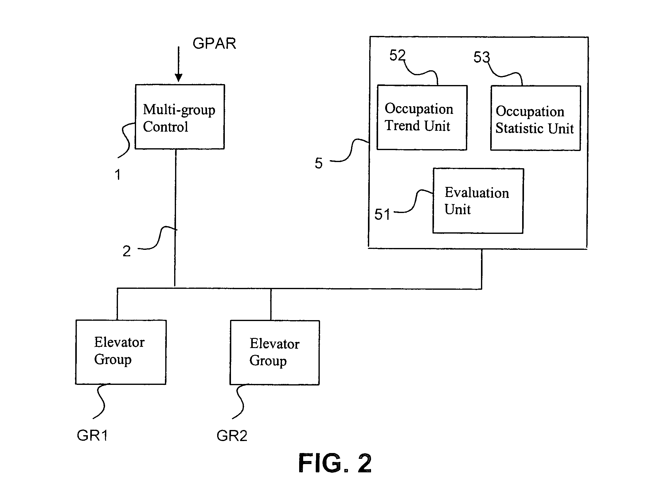
[0015]A statistics unit is provided in an advantageous embodiment of the invention. The statistics unit receives from the multi-group control, already when each changing passenger enters their first destination call, information as to the approximate time of arrival at the changeover floor. The multi-group control also transmits to the statistics unit the approximate boarding time. The exact boarding time is communicated after boarding has taken place. When the exact exiting time of the changing passengers on the changeover floor is known, this, together with the approximate time for boarding the connecting elevator, is communicated to the statistics unit VSE. As soon as the exact time of arrival of the connecting elevator is known, the multi-group control informs the statistics unit of the exact time of boarding the connecting elevator. This allows the statistics unit to maintain a future-oriented occupation statistic of the changeover floor, which is constantly made more precise with the notification of the exact arrival and departure times of each passenger.
[0016]Additionally, in an advantageous embodiment of the invention, the statistic of the occupation trend is maintained by the statistics unit. The positive or negative change in the number of persons on the changeover floor per interval of time is calculated. The statistics unit can use the approximate parameters to calculate a leading occupation of the changeover floor and a leading occupation trend. The statistic of the occupation trend complements the information regarding the number of passengers on the changeover floor, so that the correct conclusions regarding the development of the future occupation of the changeover floor can be drawn. By means of the leading statistic, the transportation capacity can be adapted in good time to the increasing or decreasing number of passengers on the changeover floor.
[0017]By the use of building-specific parameters, when a threshold value of the transportation capacity is exceeded, the transportation capacity of the collecting elevator group can be increased. When this is done, the transportation capacity of the delivering group is kept unchanged, the building is optimally filled or emptied, and the changeover floor is not overfilled.
[0019]The above measures cause only small reductions in the otherwise high convenience of a destination-call control. This manifests itself as full utilization of the car capacity and optimization of the waiting time depending on the time of arrival of the delivering elevator group. With the given peak load, the time to destination remains optimal for the totality of the changing passengers.

Problems solved by technology

These queues are caused mainly by unequal transportation capacities of the delivering and collecting elevator groups.
The problem of possible overfilling of the changeover floor can also arise when changing between zone systems.
The amount of space available on the changeover floors is usually limited, and cannot be increased without very great constructional and financial outlay.
However, these devices provide only inexact information concerning occupation of the changeover floors.
Furthermore, with these devices it is only possible to reduce or optimize the delivering transportation, and thereby avoid overfilling of the changeover floor and even greater delay in the transportation of passengers, at the cost of the overall transportation volume.
With this system, no exact forecast can be made of where the individual passengers travel to, or how many passengers are present on the changeover floor and when.
Moreover, increasing the acceleration negatively affects how passengers experience the ride, so that here also, only a very limited increase in the transportation capacity can be achieved.
These measures do not allow any really noticeable increase in the transportation capacity to be achieved.

Method used


Image

  • Zonally operated elevator installation and method for control thereof
  • Zonally operated elevator installation and method for control thereof
  • Zonally operated elevator installation and method for control thereof

Examples


Embodiment Construction

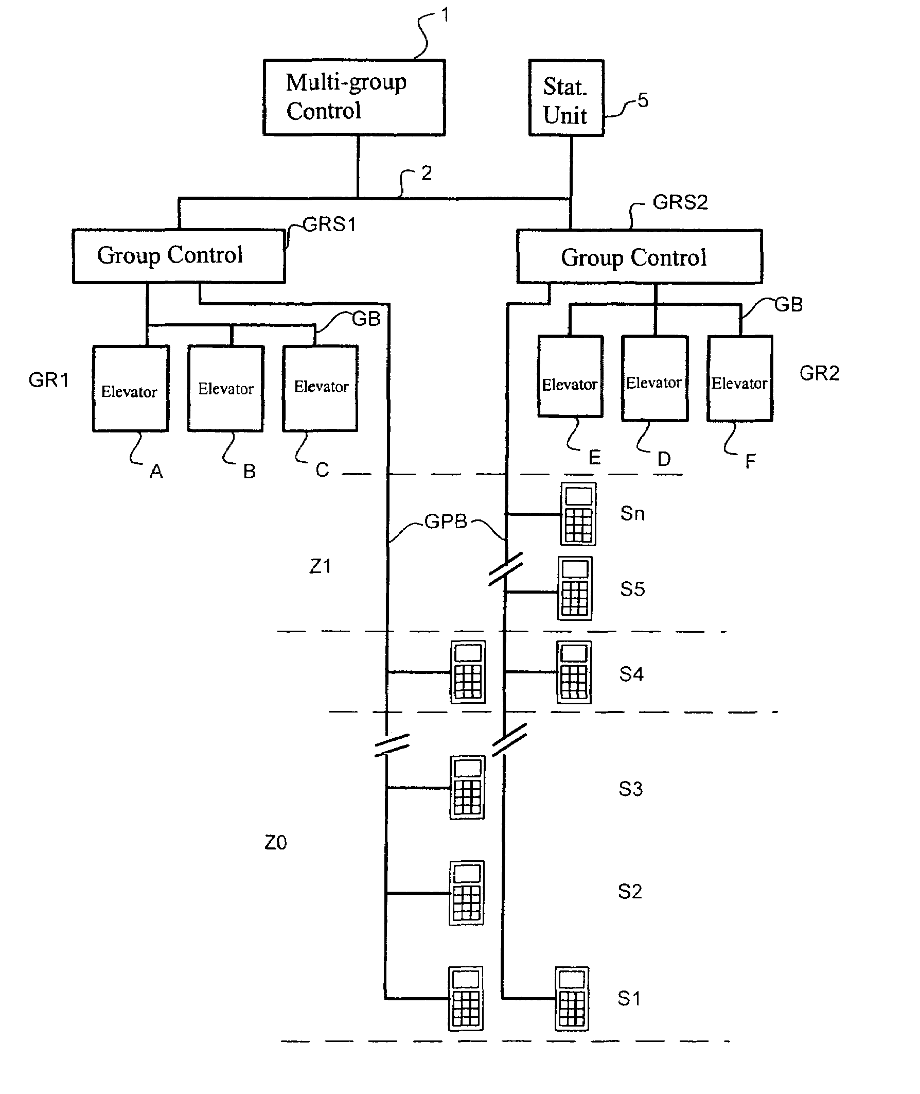
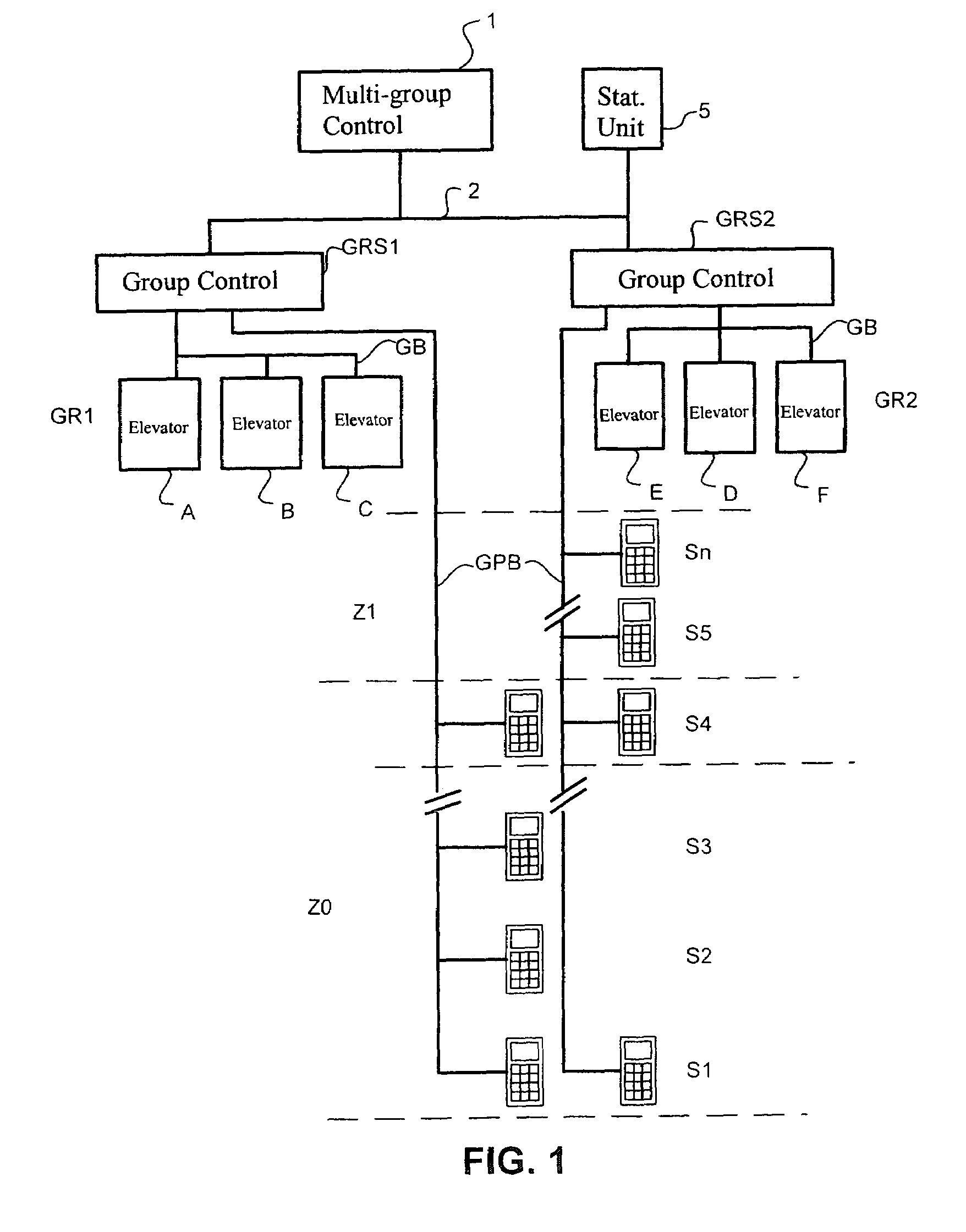
[0027]FIG. 1 shows diagrammatically the construction of an elevator installation. The building is divided into several zones, Z1, Z0. Each zone comprises several floors. Zone Z0 comprises floors S1 to S4, and zone Z1 comprises floors S4 to Sn. In these zones, the elevators A–F are used for the transportation of passengers. The elevators A–F are divided into elevator groups GR1 and GR2. The elevators are controlled via a destination-call control device ZEG (not shown). The elevator group GR1 transports the passengers in zone Z0 from floor S1 to S4, and the elevator group GR2 transports the passengers in zone Z1 from floor S4 to Sn. It is also possible to reach floor S1 with the elevator group GR2. The elevators of the first elevator group GR1 are controlled by group controls GRS1, and group controls GRS2 control the elevators of the second elevator group GR2. The elevators are connected via a group bus GB to the group controls GRS1 and GRS2, respectively. The individual floors are co...


PUM


Abstract

A method for controlling a zonally operated elevator installation, wherein on a changeover floor changing between zones is made possible, and wherein with a delivering elevator group and a collecting elevator group transportation to and from the changeover floor is realized, and wherein a trip destination is entered via a destination-call control by each passenger to be transported. An elevator installation for zonal operation in buildings with several elevators, wherein each elevator group contains at least one destination-call input device for registering the destination of a passenger. Each elevator is assigned to an elevator group, the building is divided into zones, and a changeover floor for changing between the elevator groups is arranged between the zones. The delivering elevator group and the collecting elevator group are combined into a multi-group which is controlled by a multi-group control. Using the trip-destination entries and a statistics unit, the number of passengers who will change from the elevator group on the changeover floor is determined by the multi-group control. The elevator groups are controlled by the multi-group control depending on the number of changing passengers.

Description

BACKGROUND OF THE INVENTION[0001]The invention relates to a method for controlling a zonally operated elevator installation, wherein on a changeover floor changing between the zones is made possible, and wherein with a delivering elevator group and a collecting elevator group, transportation to and from the changeover floor is realized, and further wherein a trip destination is entered via a destination-call control by each passenger to be transported. The invention further relates to an elevator installation for zonal operation in buildings with several elevators, wherein each elevator group contains at least one destination-call input device for registering the destination of a passenger. Each elevator is assigned to an elevator group, the building is divided into zones, and a changeover floor for changing between the elevator groups is arranged between the zones.[0002]To meet the increasing need for transportation in tall buildings, intelligent elevator controls are used. For thi...

Claims


Application Information

Patent Timeline
Patent Type & Authority Patents(United States)
IPC IPC(8): B66B1/20
CPCB66B1/20
Inventor KOSTKA, MIROSLAVSTEINMANN, KURT
Owner INVENTIO AG
Learn More