
Protective spool dispenser and cutter

Active Publication Date: 2006-10-24
NB PROPERTIES
View PDF33 Cites 17 Cited by
  • Summary
  • Abstract
  • Description
  • Claims
  • Application Information

AI Technical Summary

Benefits of technology

[0009]A dispenser having a cutting mechanism is provided. The dispenser includes a box-like outer frame for protecting a spool of wire or line. A cross bar is secured to the outer frame, preferably from adjacent corner members. An elongated, cylindrical receiving arm for holding a spool of line extends from the crossbar into an area defined by the outer frame. A first end of the receiving arm is secured to an intermediate position on the crossbar. A second end of the receiving arm is unsecured. The receiving arm includes a tensioning spring, and a pair of retaining washers. A spool of line may be easily passed through an open portion of the skeletal outer frame, and slid onto the receiving arm. The spool is positioned between the two washers, and prevented from free spinning by frictional forces created by the tensioning spring. A fastening pin holds the spool and outer washer in place.

Problems solved by technology

However, prior designs have not always been satisfactory.
For example, many spool holder designs fail to prevent snarling, kinking, tangling and looping of wire on a coiled spool, particularly during unwinding or dispensing of the wire from the spool.
If the wire or line is relatively lightweight, such as plastic line or cord, the spool may be especially prone to spinning freely and thereby unwinding.
Although such designs protect the wire, they do not provide an efficient or convenient dispensing means, particularly when a relatively large quantity of wire or line must be dispensed.
It is often difficult to ascertain how much wire or line is remaining on the spool.
In addition, it is often difficult to replace an exhausted spool with a new spool of line, given the housing of such dispensers must be disassembled to replace the exhausted spool.
Although such designs provide some advantages, they often fail to provide adequate protection for the spool.
All of the equipment is commonly transported from site to site in a pick-up truck bed or an open trailer, and is frequently subject to jostling, shifting and / or bumping with other equipment.
Many trimmer line spools are easily damaged if unprotected, particularly during transport of the spools and equipment.
If the plastic spool is damaged, the plastic line may become tangled, kinked, or unwound.
The line must then be de-tangled, organized, or simply discarded, thereby increasing costs.
Trimmer line spools are relatively expensive.
Although multiple spools may be positioned on such carts or caddies, they often fail to prevent free spinning when unwinding wire from the spools.
In addition, many fail to provide adequate protection to the spools.
Furthermore, they are typically cumbersome and bulky.
Although carts having wheels may be adequate for some applications, they are not easily portable from site to site, especially if the cart or caddy must be lifted into a truck or trailer.
However, replacement of exhausted spools often requires disassembly of the mounting rods from the side planks.
In addition, many such designs fail to address the problem of free spinning of the line or wire from the spool.
Many conventional dispenser designs fail to provide any cutting means.

Method used


Image

  • Protective spool dispenser and cutter
  • Protective spool dispenser and cutter
  • Protective spool dispenser and cutter

Examples


Embodiment Construction

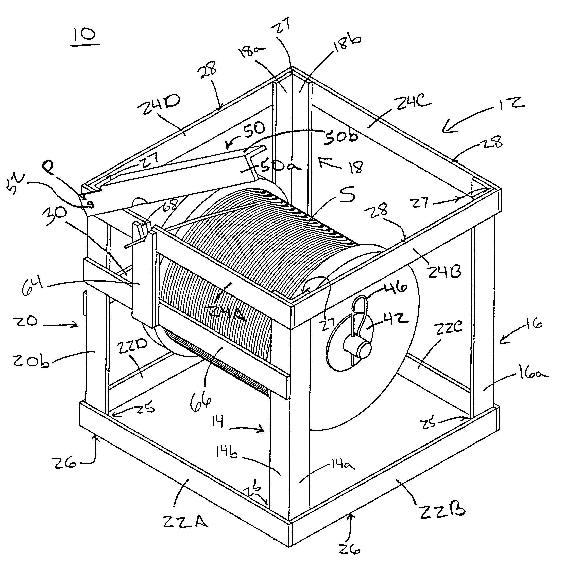
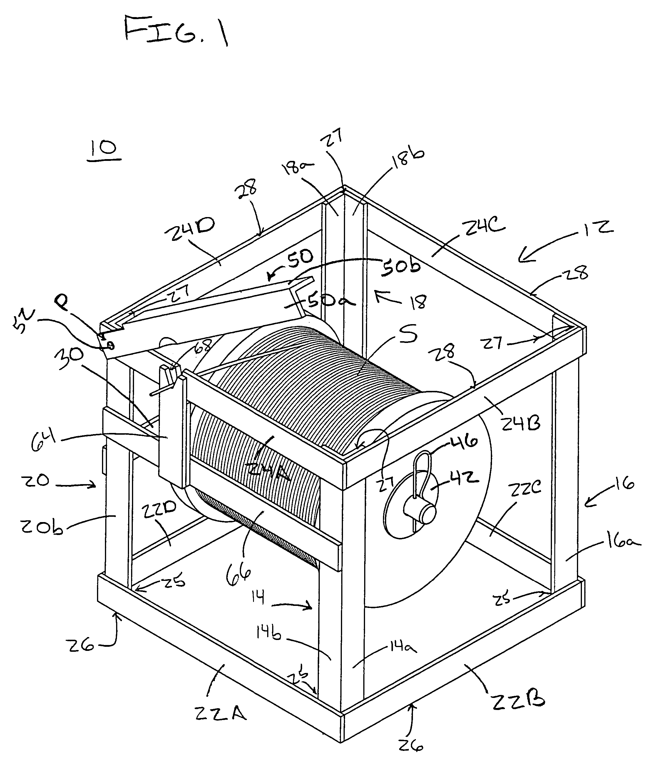
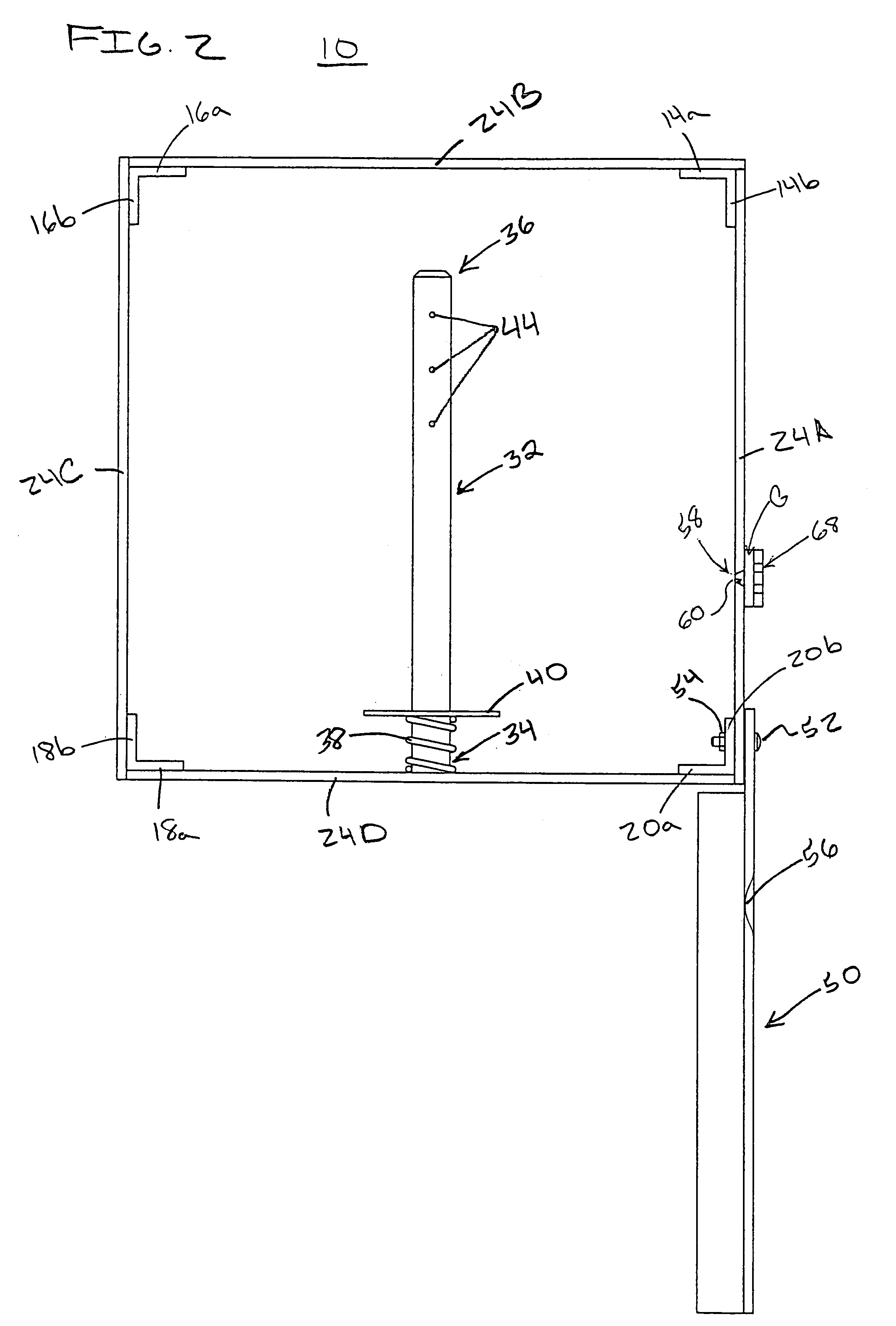
[0024]As best shown in FIG. 1, a spool dispenser 10 comprises a box-like outer frame 12 for protecting a spool S of wire or line. In a preferred embodiment, outer frame 12 includes four, L-shaped corner members, 14, 16, 18, 20. As best shown in FIG. 2, corner members 14, 16, 18, 20 include first legs 14a, 16a, 18a, 20a, and second legs 14b, 16b, 18b, 20b, respectively. Lower sidebars 22A, 22B, 22C, and 22D extend between coplanar legs of corner members 14, 16, 18, 20. Lower sidebar 22A extends from second leg 14b to second leg 20b; lower sidebar 22B extends from first leg 14a to first leg 16a; lower sidebar 22C extends from second leg 16b to second leg 18b; and lower sidebar 22D extends from first leg 18a to first leg 20a. Upper sidebars 24A, 24B, 24C and 24D are also provided, and similarly extend between coplanar legs of corner members 14, 16, 18, 20.

[0025]Lower and upper sidebars 22A–D, 24A–D are secured to opposite ends of each corner member 14, 16, 18, 20 to form box-like outer...


PUM

PropertyMeasurementUnit
Lengthaaaaaaaaaa
Areaaaaaaaaaaa
Strengthaaaaaaaaaa

Abstract

The present invention relates to a protective spool dispenser that is portable, efficient and convenient for dispensing line. The dispenser has four corner members and upper and lower sidebars, forming a box-like outer frame. A crossbar extends between two adjacent corner members. A spool-receiving arm extends from the crossbar. The end of the spool-receiving arm opposite the crossbar is unsecured, so that a spool of line may be easily slid onto the arm. The arm includes a tensioning spring, two washers and a fastening pin. The spool is sandwiched between the two washers. Free spinning is prevented due to the tensioning spring. The disclosed dispenser also preferably includes a cutter mechanism for cutting line to desired lengths.

Description

CROSS-REFERENCE TO RELATED APPLICATION AND CLAIM TO PRIORITY[0001]This application is based on provisional application Ser. No. 60 / 466,722, filed May 1, 2003, for James D. Maxey, the disclosure of which is incorporated herein by reference and to which priority is claimed under 35 U.S.C. §120.FIELD OF THE INVENTION[0002]The present invention relates to a protective spool dispenser that is portable, efficient and convenient for dispensing line. The dispenser has four corner members and upper and lower sidebars, forming a box-like outer frame. A crossbar extends between two adjacent corner members. A spool-receiving arm extends from the crossbar. The end of the spool-receiving arm opposite the crossbar is unsecured, so that a spool of line may be easily slid onto the arm. The arm includes a tensioning spring, two washers and a fastening pin. The spool is sandwiched between the two washers. Line from the spool is prevented from free spinning due to the tensioning spring. The disclosed d...

Claims


Application Information

Patent Timeline
IPC IPC(8): B26D7/00A47F13/04B23D29/02B26D1/30B65H49/32
CPCA47F13/045B23D29/023B26D1/30B65H49/32Y10T83/896Y10T83/8812
Inventor MAXEY, JAMES DEWEY
Owner NB PROPERTIES
Learn More