
Card interface device

a card and interface technology, applied in the direction of casings/cabinets/drawers, instruments, casings/cabinets/drawers details of electrical appliances, etc., can solve the problems of device and card damage, inability to function properly, lack of durability, etc., to achieve the effect of preventing accidental switching or turning on or off of the switch

Inactive Publication Date: 2006-10-17
YAMAICHI ELECTRONICS
View PDF7 Cites 40 Cited by
  • Summary
  • Abstract
  • Description
  • Claims
  • Application Information

AI Technical Summary

Benefits of technology

The present invention relates to a card interface device with a main housing body, a lid portion, a concave lock, a locking protrusion, and a hooking piece. The hooking piece has a spring portion and an arc-shaped protrusion that comes into contact with the locking protrusion to secure the lid in the closed state. The device also includes a switch pressing member that presses the switch when the lid is closed. The invention provides various configurations for the locking protrusion, hooking piece, and switch pressing member, which can be adapted based on the needs of the device.

Problems solved by technology

If the contact is not perfect, the device and the card may be damaged or may not function properly.
However, the turning axis of the lid has to be very small and the cam also becomes small in this structure for a miniaturized device, so that the axis and the cam driving the switch may become strained and result in lack of durability.
Furthermore, instability such as turning on or adversely turning off of the switch may take place when the lid is not completely closed.

Method used


Image

  • Card interface device
  • Card interface device
  • Card interface device

Examples


first embodiment

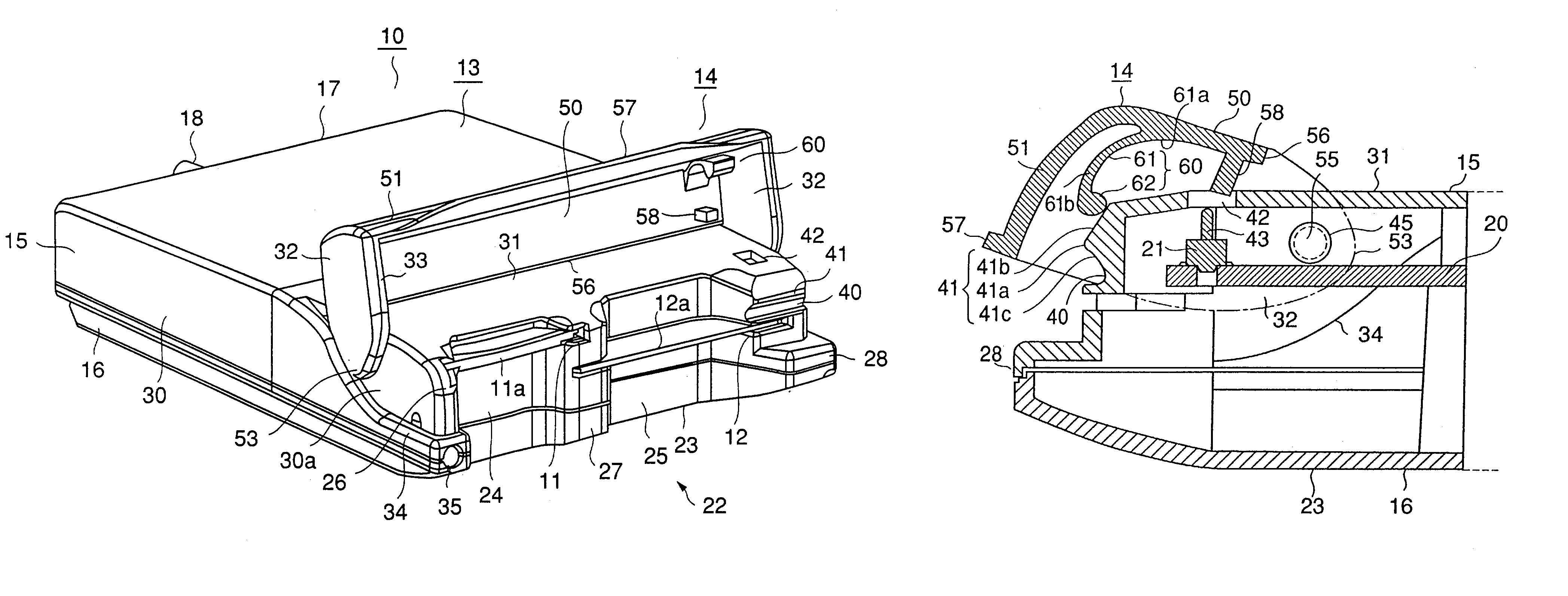
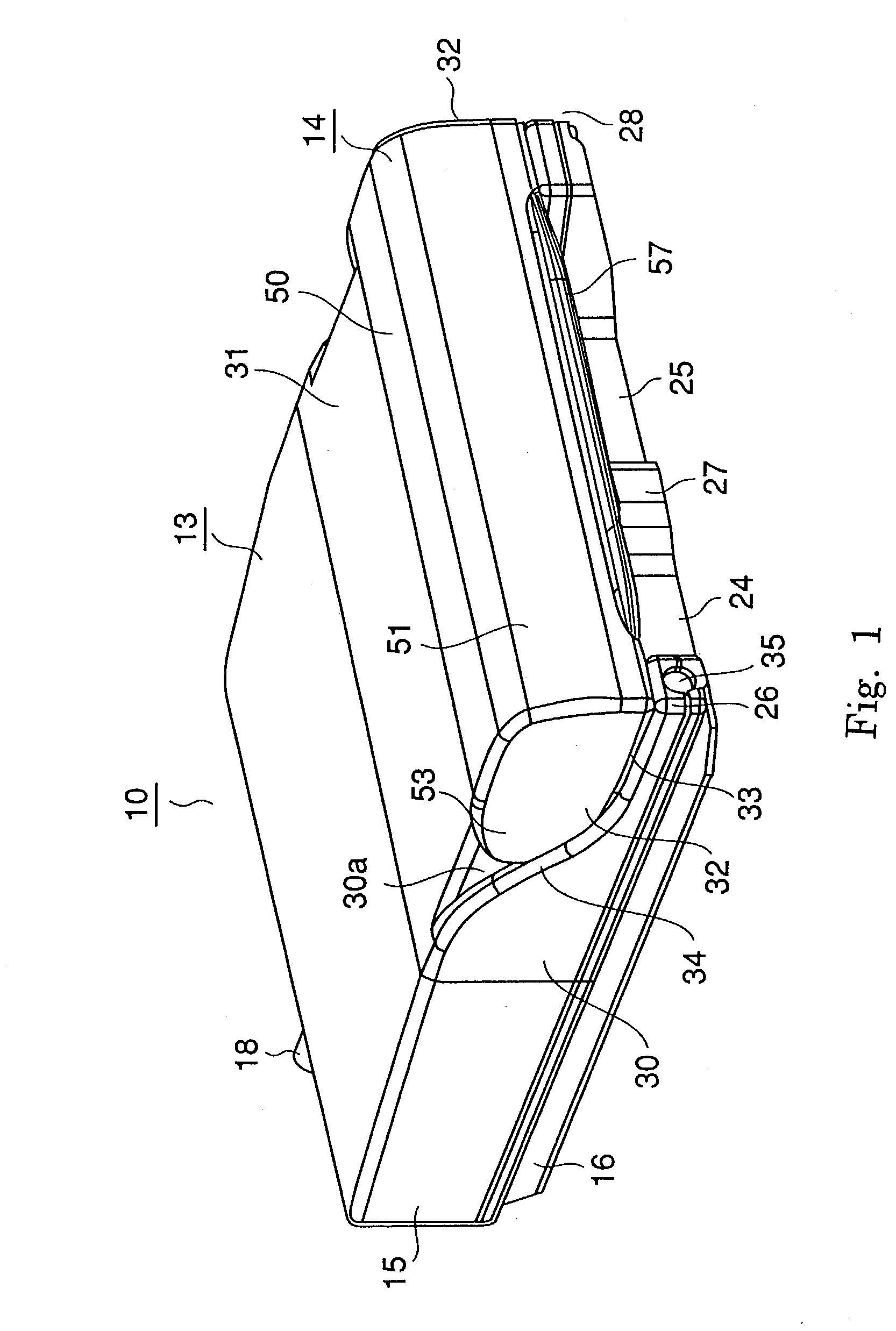
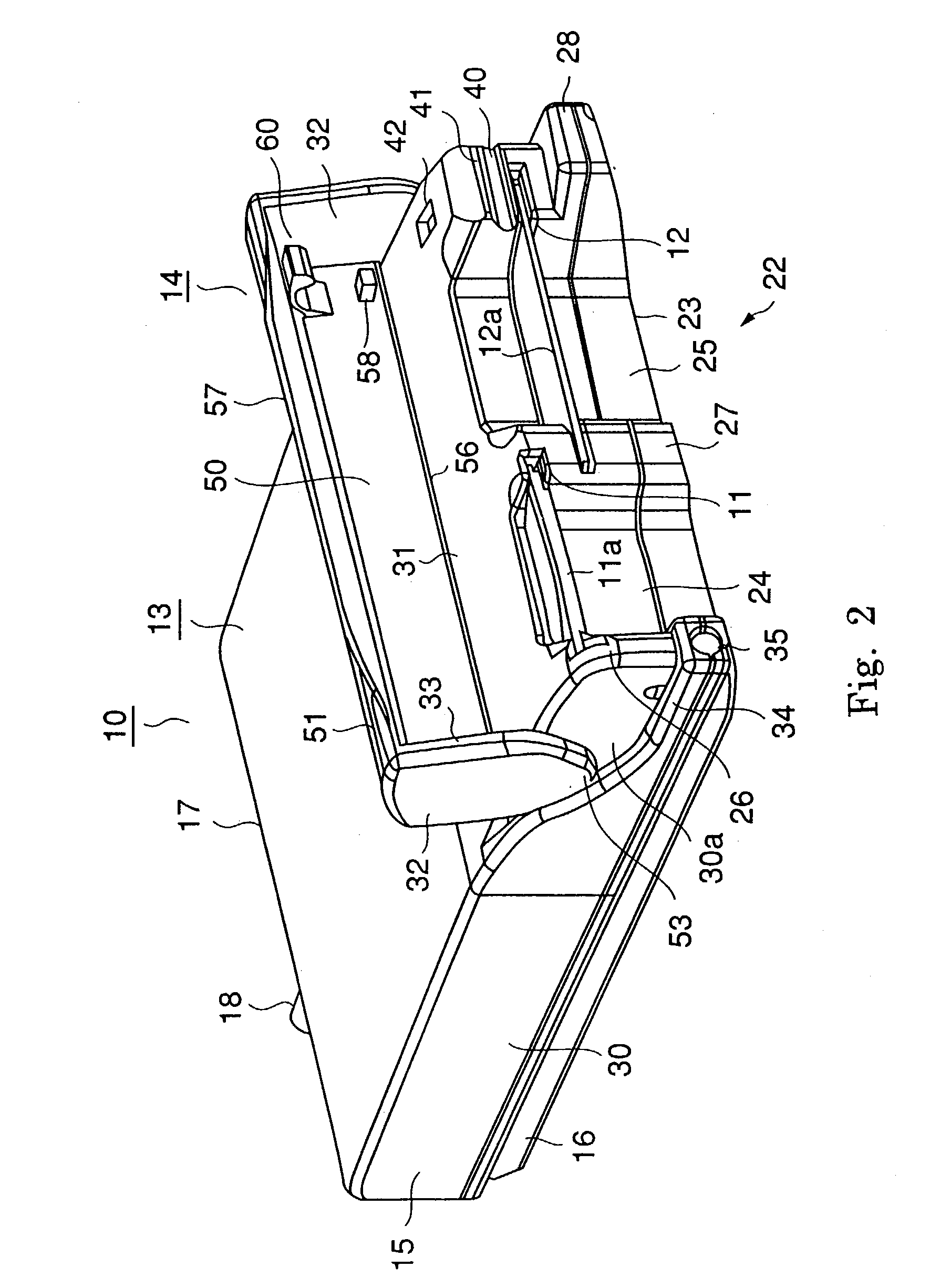
[0036]FIG. 1 to FIG. 5 show the first embodiment of the present invention.

[0037]This embodiment is applied to a card interface device, which is connected to an electronic device such as an information terminal or a digital camera, to read and write a small-sized memory card. The small-sized memory card has a variety of standards that have different outlines and different terminals, for example Smart Media (trade name) or Compact Flash (trade name). Therefore, interfaces corresponding to plural types of cards are necessary. An apparatus 10 of this embodiment has a construction comprising card-loading slots (opening portions) 11 and 12 into which different types of memory cards 11a and 12a are inserted respectively, and being connected to a main body such as a computer via a connector, such as USB (Universal Serial Bus).

[0038]The card interface device 10 comprises a housing portion 13 accommodating a main body and a lid portion 14 opening or closing about the housing portion. The hous...

second embodiment

[0051]This embodiment is characterized in that a part of the front end of the lid portion is formed as a hooking piece. Referring to FIG. 6 and FIG. 7, explanation will be carried out hereinafter. Each part denoted by the same mark as the first embodiment represents the same part of the first embodiment.

[0052]On the front part 22a of the housing portion, memory card insertion slots 11a and 12a corresponding to two kinds of cards are located at a different height from the bottom 23 of the housing and also shifted horizontally to each other. To facilitate insertion of cards, recesses 24 and 25, which make easy for an operator to pinch a card with his / her fingers and thumb, are formed at the front part near the center of each slot. Thus projecting parts 26, 27, and 28 are to be formed on the front part 22a, interposing the two recesses 24 and 25, and intervening between them.

[0053]The lid portion 14a is located on the front part of the top housing 15. Therefore, the projecting parts 26...


PUM


Abstract

In a structure where the lid portion is mounted on the main housing body comprising apertures and in such a manner as to turn freely thereon, the concave lock portion and the locking protrusion adjacent thereto capable of locking the lid in the closed state are located in the aperture side of the main housing body. The lid portion is provided with the hooking piece comprising the spring portion and the arc-shaped protrusion. When the lid portion turns to open or close the aperture portion, the arc-shaped protrusion comes into contact with the locking protrusion under pressure with the spring portion, in order that a force opposing to the turning direction may be applied thereto before and after it passes through the locking protrusion, to keep the lid portion in two states i.e. the open state and the closed state.

Description

CROSS-REFERENCES TO RELATED APPLICATIONS[0001]This application is based upon and claims the benefit of priority from the prior Japanese Patent Application No. 2002-164174, filed on Jun. 5, 2002.BACKGROUND OF THE INVENTION[0002]1. Field of the Invention[0003]The present invention relates to a card interface device comprising a housing having a switching function on a lid.[0004]2. Related Art[0005]It has been required that input and output of a card interface device or a control device thereof can be turned on or off in accordance with open or close of a lid thereof, thereby to prevent the apparatus from being damaged and to improve reliability thereof. In a structure where a card is inserted into, for example, an input / output terminal of an interface of a personal computer or a loading slot for a memory card of a portable terminal or a digital camera, it is necessary that operation should be carried out under the condition that the card is inserted therein and is completely into cont...

Claims


Application Information

Patent Timeline
Patent Type & Authority Patents(United States)
IPC IPC(8): H05K7/14H05K7/18H05K5/03G06K7/00G06K17/00H01H3/16H01H9/02
CPCG06K7/0013G06K13/0875
Inventor SAITO, MASAAKITAKAHASHI, KEI
Owner YAMAICHI ELECTRONICS
Learn More