Torque anchor

a technology of torque anchors and torque rods, which is applied in the direction of tubing catchers, fluid removal, borehole/well accessories, etc., can solve the problems of affecting the operation of the pump, and affecting the operation of the torque anchor

Inactive Publication Date: 2006-10-17
SAMPWELL TESTING SERVICES COBA PROGRESSIVE TECH
View PDF14 Cites 11 Cited by
  • Summary
  • Abstract
  • Description
  • Claims
  • Application Information

AI Technical Summary

Benefits of technology

[0009]It is yet another feature of the present invention to provide an anchor that can be used repeatedly between rebuilds.
[0012]According to a further aspect of the present invention, there is provided a method for anchoring a device against rotation in a well bore, comprising the steps of non-rotatably connecting the device to a mandrel disposed either above or below the device; surrounding at least a portion of the mandrel with a cylindrical housing that is rotatable relative to said mandrel, said housing having associated therewith a first set of anchor members normally biassed into frictional contact with the well bore to hold the housing stationary relative thereto, and a second set of anchor members actuatable in response to rotation of said mandrel for movement between a first retracted position and a second well bore gripping position, wherein gripping of the well by said second set of anchor members prevents further rotation of said mandrel.

Problems solved by technology

The problem however is that the drive rods themselves store a considerable amount of energy in the form of twist.
When the motor is stopped, the rods untwist to release their stored torque, and the release can be violent, made worse by the weight of the oil in the tubing from the pump to the surface, resulting in speeds approaching 20,000 rpm.
Because the pump anchor has become unset in response to the counterclockwise (to the “left”) unwinding of the rods, the pump is unrestrained and whips around inside the well casing causing major damage to the pump and everything in its vicinity.
The torque can also wildly spin the sheaves and pulleys that deliver torque from the motor to the drive rods which can cause additional failures and endanger anyone close by.
They must be recovered to the surface then refaced or redressed after each use, which limits their utility.

Method used


Image

  • Torque anchor
  • Torque anchor
  • Torque anchor

Examples


Embodiment Construction

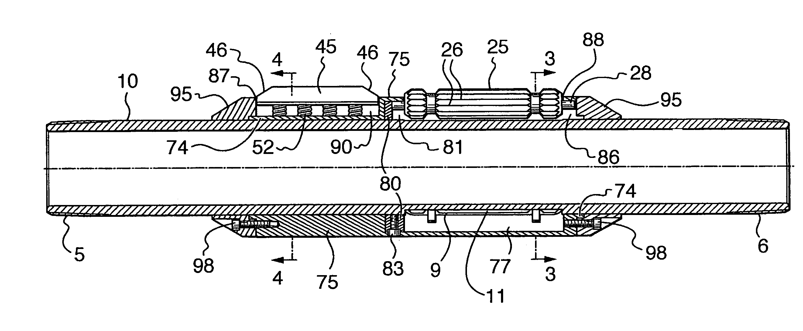
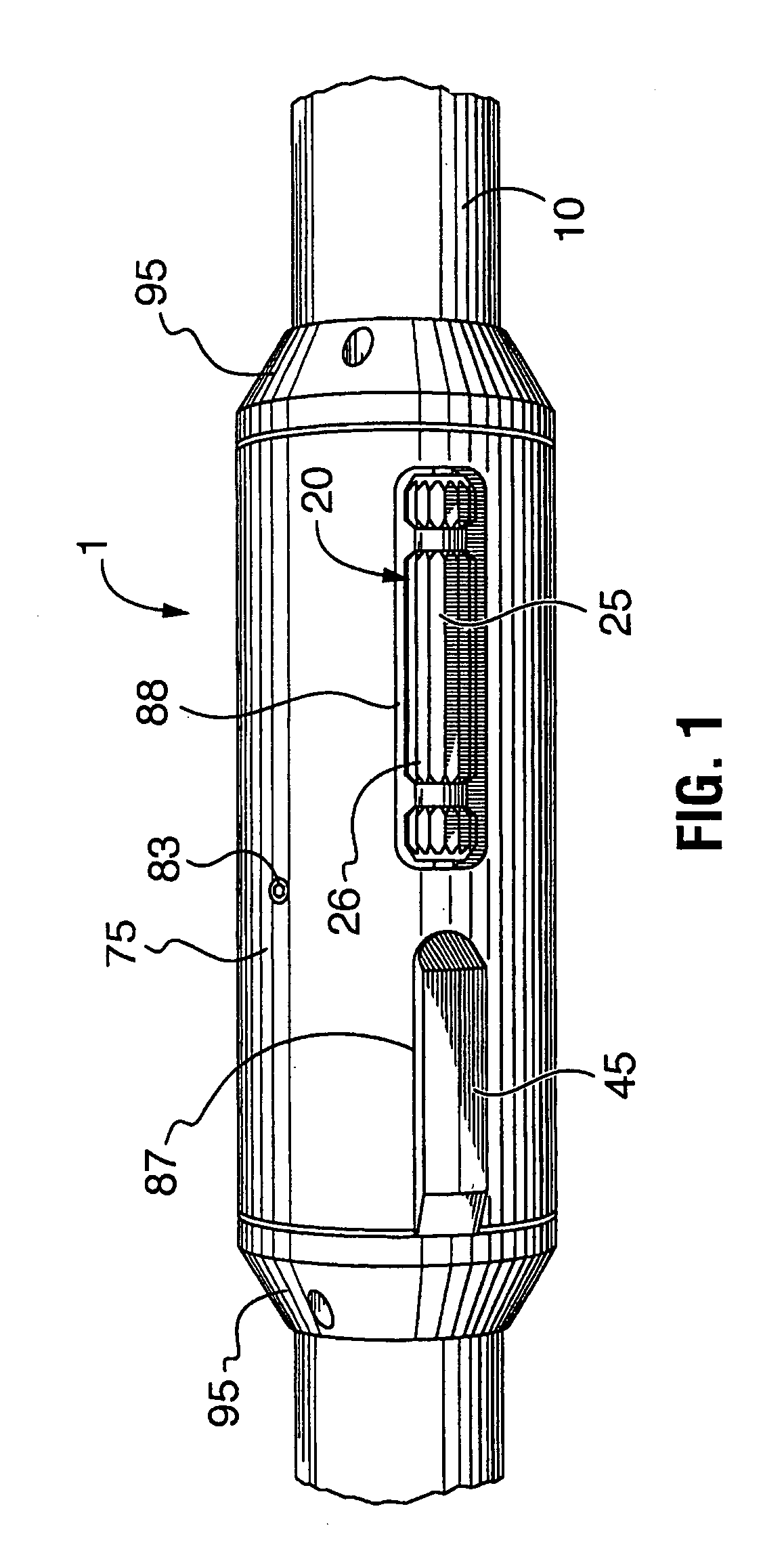
[0021]Referring initially to FIG. 1, the principal components of the present torque anchor 1 include a longitudinally extending tubular mandrel 10, one or more cylindrical rotatable anchoring slip assemblies 20 that can be biassed against the well casing by the mandrel to prevent rotation of the anchor, frictional drag blocks 45 that are continuously biassed against the casing and a rotatable slip housing 75 that retains the slip assemblies and drag blocks in their operational positions.

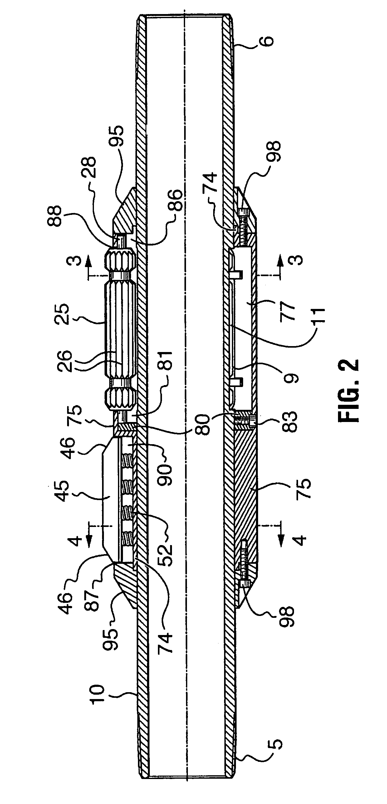
[0022]With reference to FIGS. 2 and 7, mandrel 10 is a hollow tubular member threaded at its opposite ends 5 and 6 for respective connection at one end to the stator of the progressing cavity pump (not shown), and at the other end to any tubing below the anchor (again not shown). At a point intermediate along its length the mandrel includes a section 9 serrated with longitudinally extending teeth 11 the configuration of which will be seen most clearly in FIG. 3. The cross-sectional shape of toothed s...


PUM


Abstract

An anchor to inhibit rotation of a device relative to an oil well casing, comprising a tubular mandrel adapted for direct or indirect connection to the device; a rotatable cylindrical housing with a plurality of apertures and able to receive at least a portion of the mandrel concentrically therethrough; a plurality of spaced apart anchoring slips disposed between the housing and the mandrel in registry with respective ones of the apertures in the housing's outer surface; a rotation mechanism associated with the mandrel to engage and then move respective ones of the anchoring slips radially towards and then into temporarily anchoring contact with the casing; and one or more drag blocks disposed in the housing in registry with respective ones of the apertures in the housing's outer surface to extend radially outwardly therefrom, each of the drag blocks being normally biased into frictional contact with the casing.

Description

BACKGROUND OF THE INVENTION[0001]Progressing cavity pumps are in increasingly common use in the oil field for production of formation fluids to the surface. The pumps comprise a fixed outer body usually referred to as a stator which connects to the production tubing in the well. Within the stator is a rotating inner component called a rotor which in cooperation with the stator pumps the formation fluids.[0002]The rotor is rotated by a string of drive rods that transmit torque from a prime mover at the well head. The prime mover is normally an electric motor that produces up to 100 horsepower and also generates very substantial torque. The drive rods extend from a drive head at the top of the well head down through the production tubing to the rotor.[0003]The inside of the stator is rubber and friction is generated as the rotor spins. If the stator is not properly anchored, it will rotate in the clockwise direction (to the “right” when viewed from above) and if not checked, the tubin...

Claims


Application Information

Patent Timeline
Patent Type & Authority Patents(United States)
IPC IPC(8): E21B23/01E21B43/12
CPCE21B23/01E21B43/126
Inventor ALDRIDGE, COLIN A.JAGERT, FRITZ
Owner SAMPWELL TESTING SERVICES COBA PROGRESSIVE TECH
Why Eureka
Try Eureka