
Method and apparatus for image processing

Inactive Publication Date: 2006-10-10
SIEMENS MEDICAL SOLUTIONS USA INC
View PDF6 Cites 30 Cited by
  • Summary
  • Abstract
  • Description
  • Claims
  • Application Information

AI Technical Summary

Benefits of technology

[0021]Having corrected the images it is possible to repeat the process using differently spaced sampling points, for instance more closely spaced s

Problems solved by technology

However, this method is not useful for images which lack recognisable geometric features.
However, it does have certain problems.
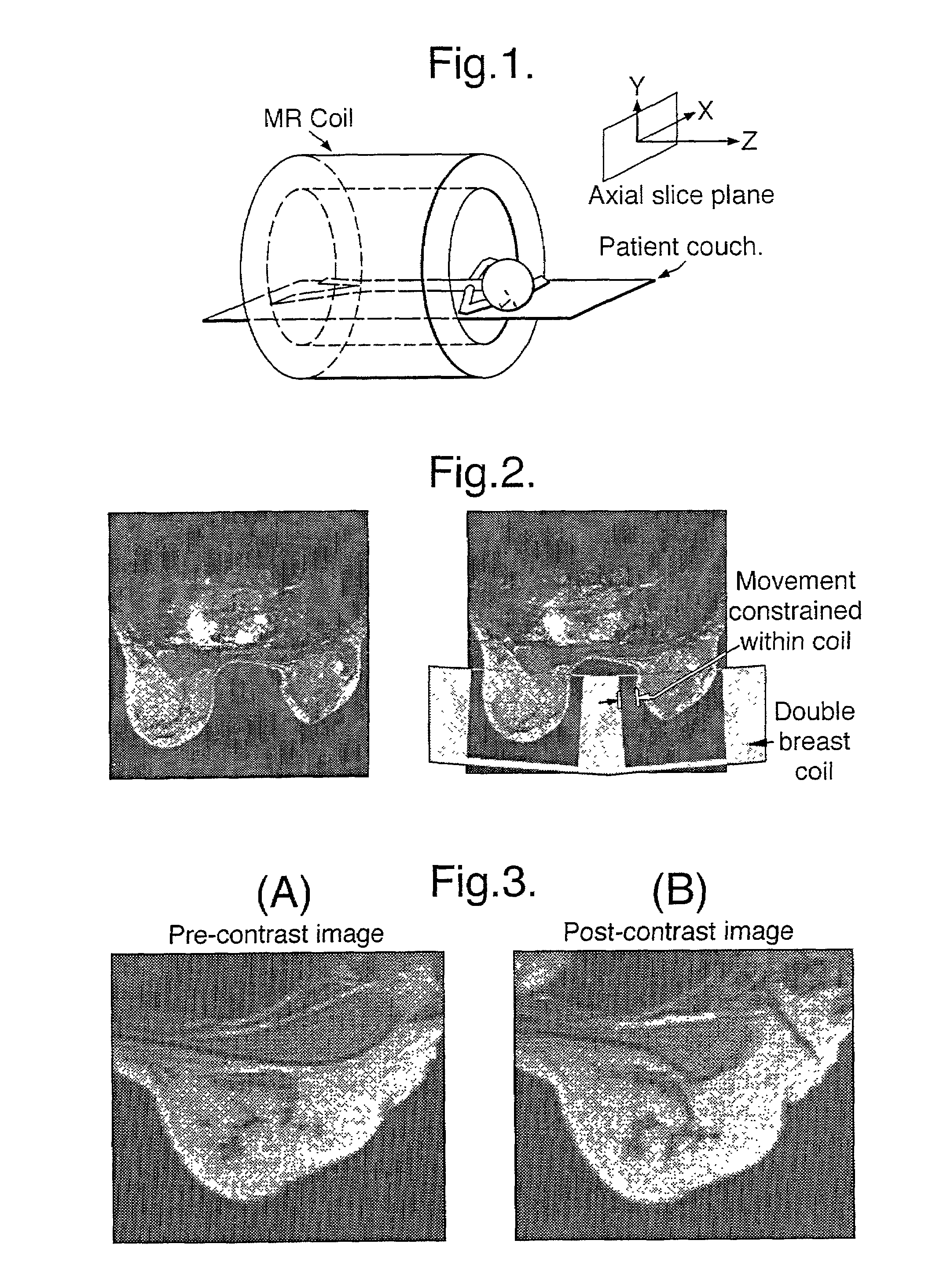
Firstly, abnormalities in the breast cannot be distinguished in a standard MRI image.
Because of the length of time over which imaging occurs, it is very likely that the patient will move during that time.
These movements make it difficult, or sometimes impossible, to interpret the succession of images because not only are the images changing through take up of the contrast agent, but also because of movement of the patient.
Such non-rigid movement is difficult to compensate for.
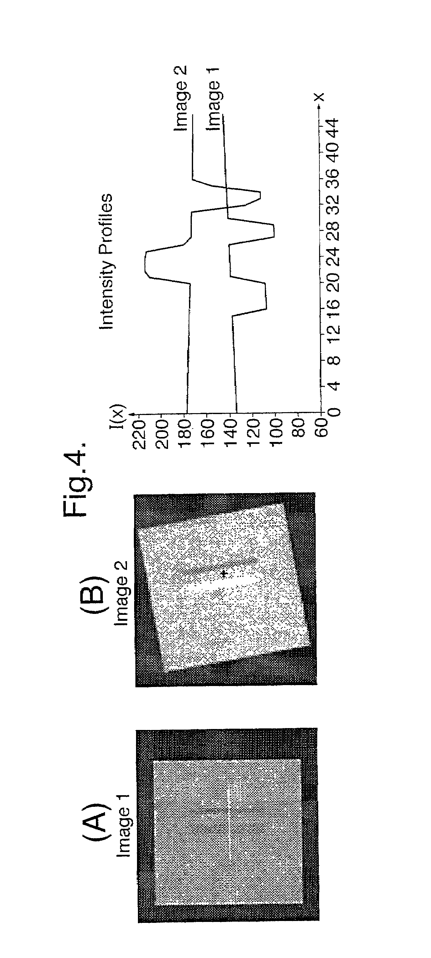
Further, because the contrast agent is being taken up during the imaging process, features which have one level of brightness in a first image will not necessarily have the same value of brightness in a subsequent one (the image is said to be non-conservative).
However, in non-rigid flow there can be several plausible motions locally and so algorithms which ignore that fact can fall into local minima which do not correspond to the ultimately optimal solution during the iterative process.
As mentioned above a problem with non-conservative images such as MRI images when a contrast agent is being dynamically taken-up, is that points of a certain intensity in one image cannot be expected to have the same intensity in another.

Method used


Image

  • Method and apparatus for image processing
  • Method and apparatus for image processing
  • Method and apparatus for image processing

Examples


Embodiment Construction

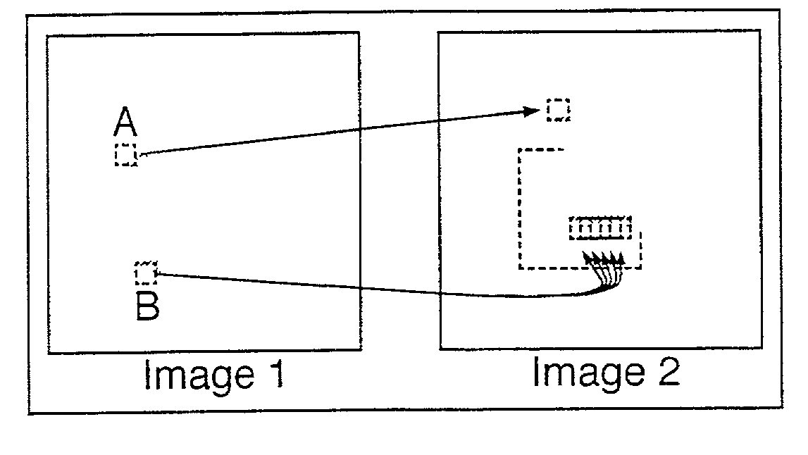
[0035]Any image registration algorithm, i.e. an algorithm for detecting and correcting for movement between images, requires a method of determining whether two sub-images represent the same part of the imaged object. In the case of breast MRI, this amounts to determining whether the two sub-images represent the same anatomical location. As mentioned above, while many prior techniques rely on recognising geometrical features, this is not suitable for all images, especially images from breast MRI. Magnetic resonance signal intensity is a subject to change between images because of the deliberately induced contrast enhancement, and this change can be of the order of 100%. Further, the deformation which results from the movement is non-rigid. Thus the method of determining whether the two sub-images represent the same physical location is important. In this embodiment of the invention this is achieved by using a “similarity measure”, of which there are several types.

[0036]One measure w...


PUM


Abstract

An example system and method for processing image data of a plurality of time-separated images of a non-rigid body to detect movement of the body involves calculating and storing, for each of a plurality of sampling points in each image, a plurality of candidate movements together with the estimated probability of each candidate. For each sampling point, the probability of each of the candidate movements is recalculated based on the stored probability of that candidate movement and the probabilities of the candidate movements at neighboring sampling points. A motion field indicative of the non-rigid body movement is generated from the recalculated probabilities.

Description

[0001]This application is the national stage of PCT / GB00 / 01020, filed on Mar. 17, 2000, which designated the United States.BACKGROUND AND SUMMARY[0002]This invention relates to a method and apparatus for processing image data, and in particular for processing a sequence of images of a non-rigid body to correct for movement of the non-rigid body between the images.[0003]There are many applications in which it is useful to detect corresponding features in successive images of a body, for instance to allow detection of the movement of the body and to correct for movement of it. Many methods have been proposed for detecting such corresponding features. The successful detection of corresponding features in successive images allows the registration of the images, i.e. allows subsequent images to be transformed to eliminate differences caused by motion.[0004]A common way to detect motion in successive images is to use landmark and segmentation based algorithms (also known as sparse matchin...

Claims


Application Information

Patent Timeline
IPC IPC(8): G06K9/00G01R33/32A61B5/055G06T1/00G06T7/20
CPCG06K9/6206G06T7/208G06T7/277G06V10/754
Inventor BRADY, JOHN MICHAELHAYTON, PAUL MICHAELSMITH, STEPHEN MARK
Owner SIEMENS MEDICAL SOLUTIONS USA INC
Learn More