
System, method and article of manufacture for shadow mapping

a technology of shadow mapping and manufacturing method, applied in the field of computer graphics, can solve the problems of difficult to achieve total visual realism, difficult to accurately represent real-world visual effects, and limited technique flexibility

Inactive Publication Date: 2006-10-10
NVIDIA CORP
View PDF0 Cites 21 Cited by
  • Summary
  • Abstract
  • Description
  • Claims
  • Application Information

AI Technical Summary

Benefits of technology

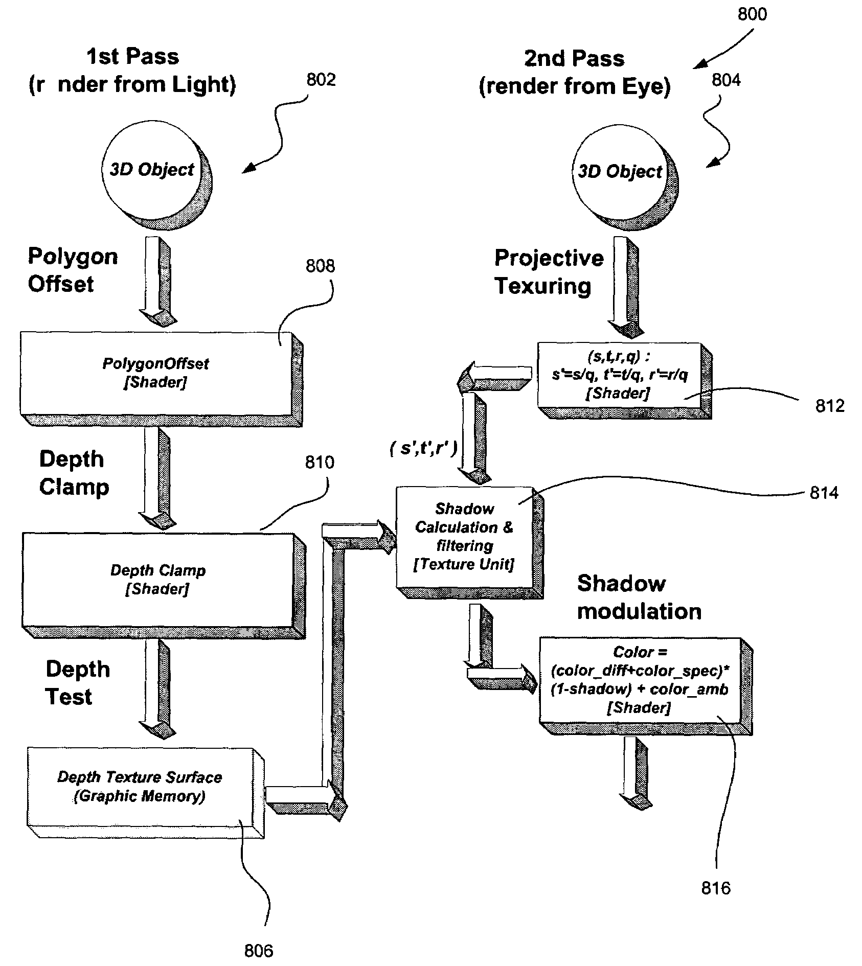
The present invention provides a system, method, and article of manufacture for shadow mapping in a graphics pipeline. The invention includes an offset operation to generate a depth value while rendering a primitive, and a value of slope associated with a triangle is identified. The depth value is then conditionally clamped to the depth gamut of the triangle based on the value of the slope. The invention also includes a technique for performing shading calculations using a shadow variable, diffuse color variable, specular color variable, and ambient color variable. The technical effects of the invention include improved shadow mapping and shading calculations in a graphics pipeline.

Problems solved by technology

A fundamental difficulty in achieving total visual realism is the complexity of accurately representing real world visual effects.
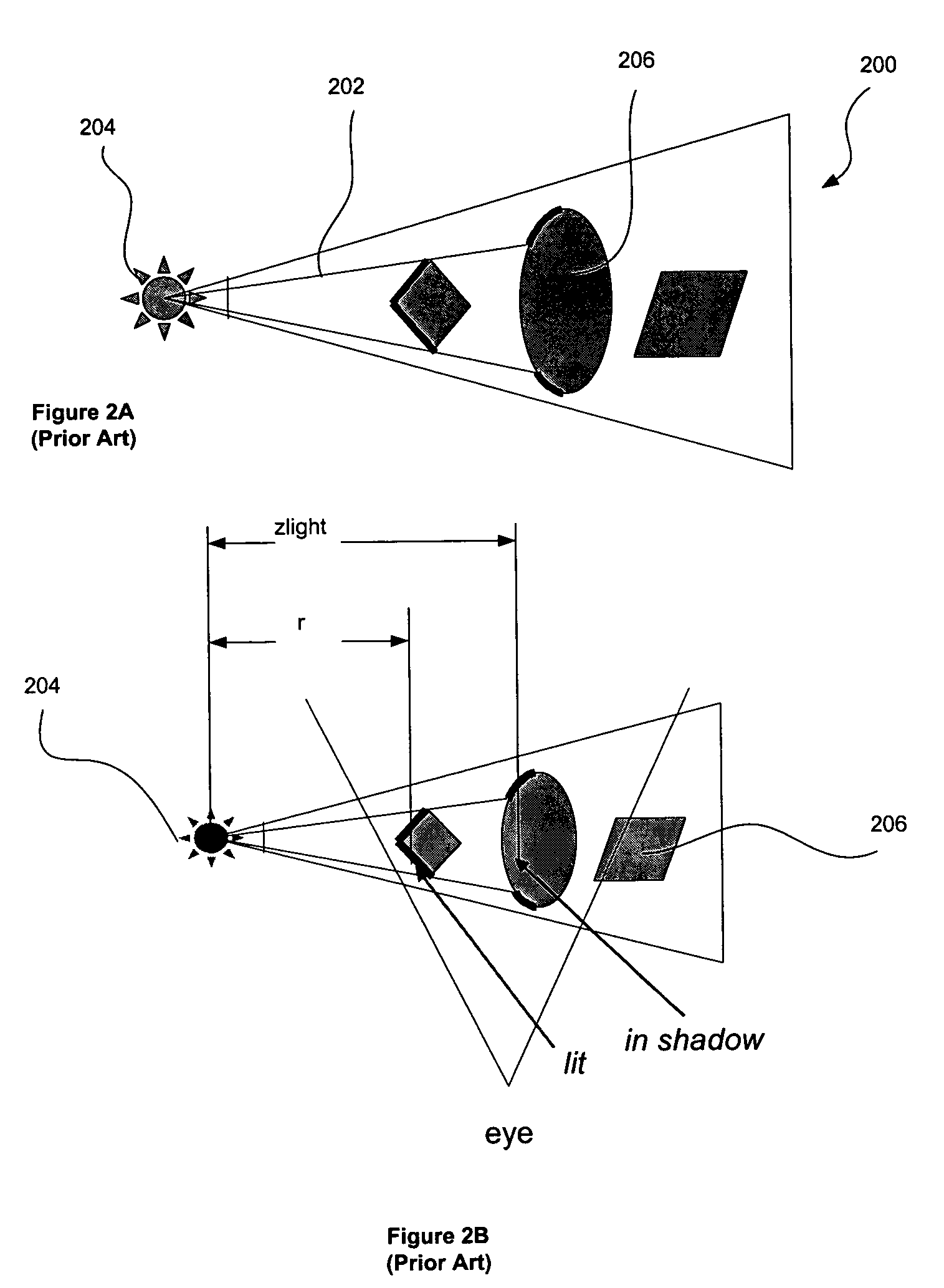
The resultant binary shadow values are then used to shade the current scanned object, resulting in shadow effects.
This can lead to erroneous results, i.e. false shadows, when using the offset equation set forth hereinabove.
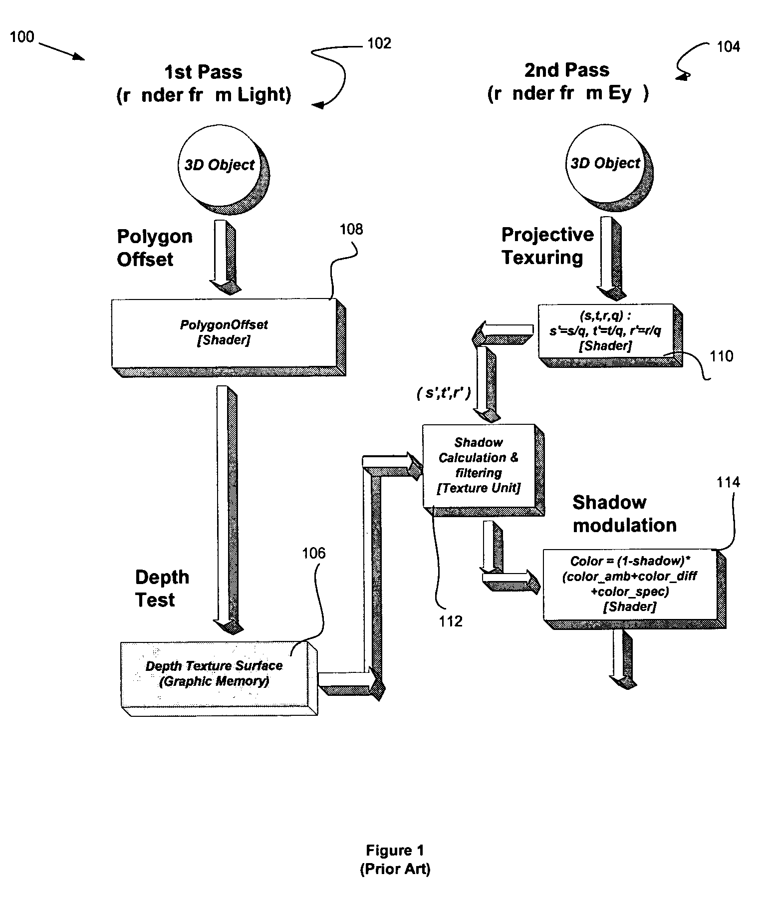
This technique is very limited in its flexibility since it shadows a superposition of diffuse color and ambient color by simply adding them before entering the pixel shading logic.

Method used


Image

  • System, method and article of manufacture for shadow mapping
  • System, method and article of manufacture for shadow mapping
  • System, method and article of manufacture for shadow mapping

Examples


Embodiment Construction

[0062]FIGS. 1–3B illustrate the prior art. FIG. 4 shows an illustrative hardware implementation of the present invention. As shown, included is a set-up module 402, a rasterizer 404, a shader module 406, a texture fetch module 408, and a combiner 410 coupled to form a portion of a graphics processing pipeline 400. For reasons that will soon become apparent, a feedback loop 409 is coupled between an output of the shader module 406 to an input thereof. It should be noted that the set-up module 402, rasterizer 404, and combiner 410 operate in a conventional manner as set forth during reference to FIG. 1. While the combiner 410 may be implemented in any desired manner, one exemplary implementation is disclosed in a application entitled “GRAPHICS PIPELINE INCLUDING COMBINER STAGES” filed Mar. 22, 1999 under Ser. No. 09 / 273,975, issued under U.S. Pat. No. 6,333,744, and naming David B. Kirk, Matthew Papakipos, Shaun Ho, Walter Donovan, and Curtis Priem as inventors, and which is incorpora...


PUM


Abstract

A system, method and article of manufacture are provided for shadow mapping while rendering a primitive in a graphics pipeline. Initially, an offset operation is performed in order to generate a depth value while rendering a primitive. Further, a value of a slope associated with an edge of the primitive is identified. Thereafter, the depth value is conditionally clamped based on the value of the slope.

Description

RELATED APPLICATION(S)[0001]This application is a continuation of application filed Dec. 5, 2000 under Ser. No. 09 / 730,639 now U.S. Pat. No. 6,690,372, which is a continuation-in-part application of a applications entitled “SYSTEM, METHOD AND ARTICLE OF MANUFACTURE FOR SHADOW MAPPING” filed Aug. 16, 2000 under Ser. No. 09 / 640,505 now U.S. Pat. No. 6,593,923; and “SYSTEM, METHOD AND ARTICLE OF MANUFACTURE FOR PIXEL SHADERS FOR PROGRAMMABLE SHADING” filed May 31, 2000 under Ser. No. 09 / 585,809, issued under U.S. Pat. No. 6,532,013, which are both incorporated herein by reference in its entirety. This application is also related to a application entitled “GRAPHICS PIPELINE INCLUDING COMBINER STAGES” filed Mar. 22, 1999 under Ser. No. 09 / 273,975, issued under U.S. Pat. No. 6,333,744, and naming David B. Kirk, Matthew Papakipos, Shaun Ho, Walter Donovan, and Curtis Priem as inventors, and which is incorporated herein by reference in its entirety.FIELD OF THE INVENTION[0002]The present in...

Claims


Application Information

Patent Timeline
Patent Type & Authority Patents(United States)
IPC IPC(8): G06T15/00G06T15/50G06T15/60
CPCG06T15/50G06T15/60G06T15/80
Inventor DONOVAN, WALTER E.PENG, LIANG
Owner NVIDIA CORP
Learn More