
Exercise ball mounted for rotation

Inactive Publication Date: 2006-10-10
HALEZ
View PDF8 Cites 54 Cited by
  • Summary
  • Abstract
  • Description
  • Claims
  • Application Information

AI Technical Summary

Benefits of technology

[0011]Depending upon how the ball is configured within the frame and what attachments are added to the frame, numerous exercises are possible. In use, the user rests a portion of their body weight on the ball and exerts an applied force to rotate the ball. It is also possible that, using the variable resistance function of the connectors that the user could “lock” the ball in a static position to facilitate additional exercises.

Problems solved by technology

Exercise balls are typically used on the surface of a floor, with some portion of the weight of the user coming to rest upon the ball, thereby causing a deformation of the ball as it is pressed between the user and the floor.
The resultant deformation adds a limited amount of resistance to the exercise.
Used in this manner, the ball adds an element of instability to the exercise.
This instability would not normally be experienced by a user with the associated exercise in the absence of the ball.
One key cause of this instability is that the ball is not secured in any manner, other than by the weight of the user.
While providing additional exercises for use with an exercise ball, this device does not address the inherent instability of exercise balls.
As discussed above, exercise balls are useful tools for exercise, but suffer from a number of limitations as a result of their ability to roll in any direction along the horizontal plane.
Exercise balls are inherently unstable.
Often this instability is not desired by the user.
This instability often makes it more difficult to isolate the desired muscle group or groups intended by a particular exercise motion.
The feeling of instability can be unnerving to inexperienced users and may even lead to injury due to loss of balance or when otherwise used improperly.
Unfortunately, this results in a concomitant reduction in support to the user.
As such, it is difficult to adjust the resistance to tailor it to the exercise and the user's needs.
Finally, because the ball is not secured by any means, it is difficult to firmly stabilize an isolated part of the user's body, such as the user's feet or hands, so as to apply a significant amount of force to be exerted during the motion of the exercise.

Method used


Image

  • Exercise ball mounted for rotation
  • Exercise ball mounted for rotation
  • Exercise ball mounted for rotation

Examples


Embodiment Construction

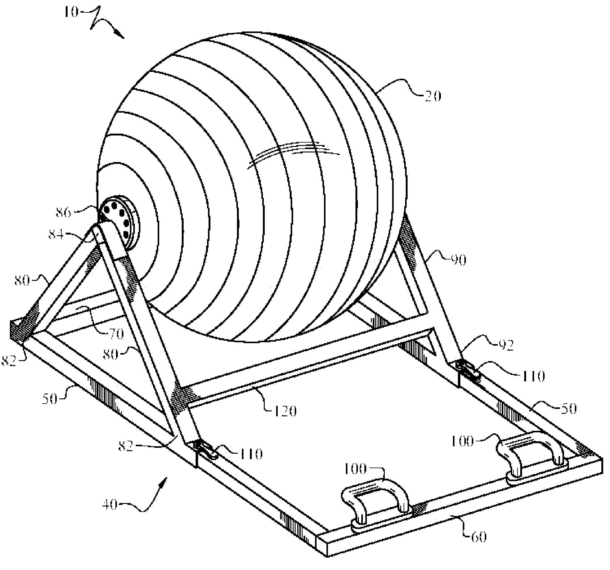
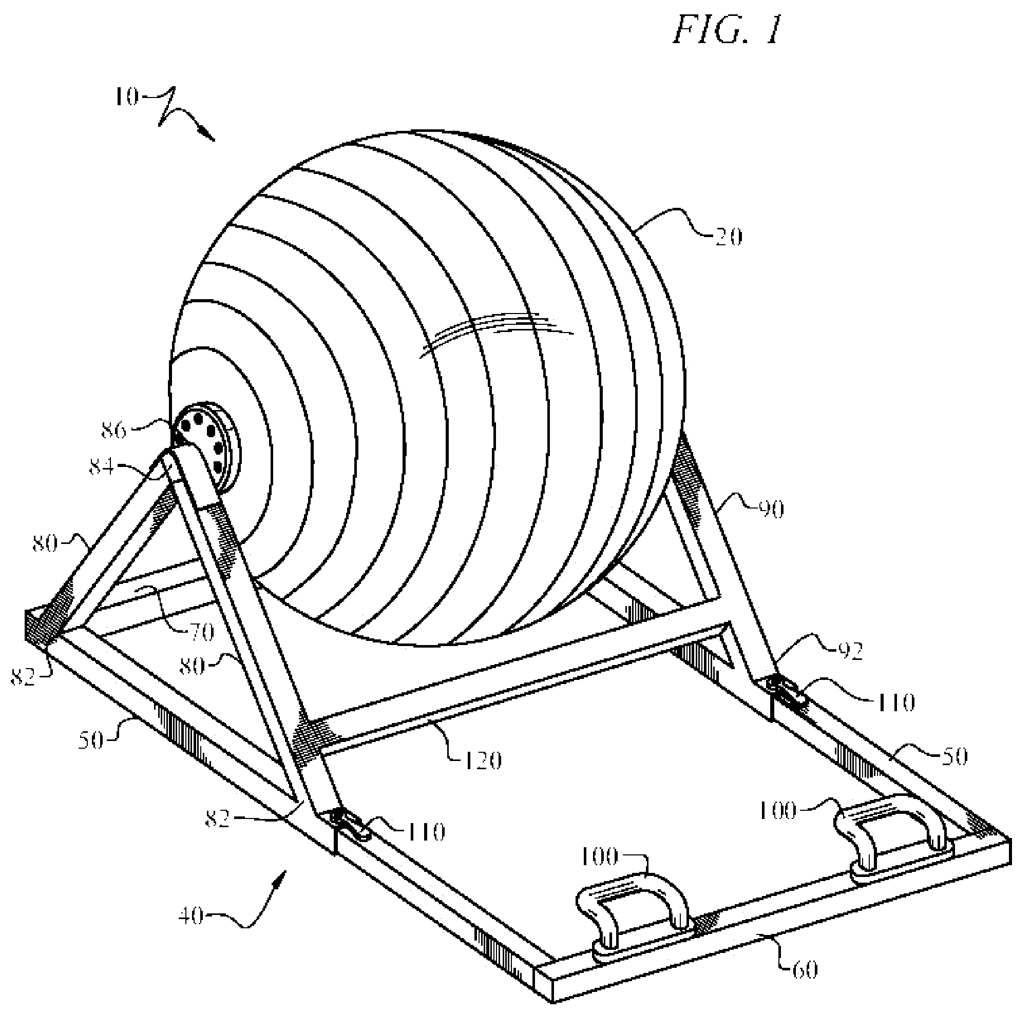
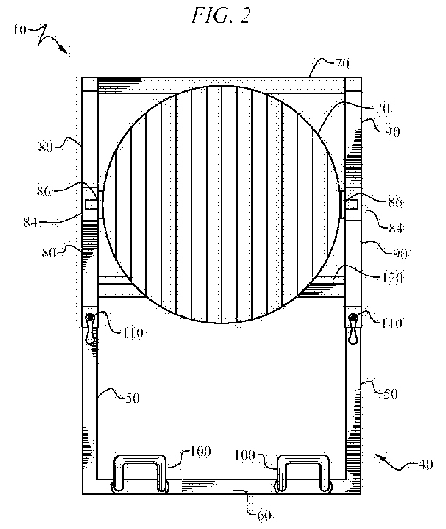
[0024]FIG. 1 shows an exercise device 10 according to an exemplary embodiment of the present invention. Exercise device 10 includes a user support means in the form of a substantially spherical, resilient ball 20 attached to a frame 40. The ball is adapted to support the weight of a user while the user performs exercises. It is contemplated that the user support means can adopt a shape other than that of a substantially spherical ball. For instance, the shape could be ovoid or cylindrical. The frame 40 rotatably supports the ball in vertically spaced relation to a support surface. The frame 40 includes a pair of longitudinally disposed base members 50 disposed in substantially parallel orientation in relation to one another. The front of the frame 40 includes a leading transversely disposed base member 60 that interconnects the respective leading ends of the pair of longitudinally disposed base members 50. The rear of the frame 40 includes a trailing transversely disposed base membe...


PUM


Abstract

An exercise apparatus for developing strength and flexibility of the arms, legs, back and abdominals of the user. The exercise apparatus is an adaptation of the exercise ball or Swiss ball. The exercise apparatus includes a large, spherically-shaped, resilient ball, a frame and a pair of connectors, the connectors rotatably connecting the ball to the frame. Various attachments may be placed on the frame to allow the user to grasp the apparatus or lock their feet to prevent unwanted motion. A mechanism can also be included in the connectors allowing the user to selectively adjust the rotation to a desired degree of resistance.

Description

CROSS-REFERENCE TO RELATED APPLICATION[0001]This application claims priority to U.S. Provisional Patent Application No. 60 / 594,463, filed Apr. 11, 2005, the contents of which are herein incorporated by reference.FIELD OF INVENTION[0002]This invention relates to an exercise device. More particularly this invention relates an exercise device based upon an exercise ball where the exercise ball is secured to facilitate rotation about an axis.BACKGROUND OF THE INVENTION[0003]An exercise ball is a large, spherical, resilient ball that can be used for a variety of exercises. These balls are also commonly referred to as a “Swiss ball”, “Swiss exercise ball”, “stability ball” or a “pilates ball.” The ball is often inflatable, made of vinyl or plastic. Alternatively, it may be made of a solid material such as foam rubber. Exercise balls were originally used for therapeutic exercises, but have been more widely adopted in recent years to develop a user's flexibility, balance and strength, inclu...

Claims


Application Information

Patent Timeline
IPC IPC(8): A63B26/00A63B71/00
CPCA63B21/143A63B21/00069A63B21/015A63B21/0442A63B23/0211A63B41/00A63B2023/006A63B2069/0062A63B2071/027A63B2208/0247A63B2225/62Y10S482/907A63B21/4015A63B69/0062A63B41/125
Inventor HALE, THOMAS J.
Owner HALEZ
Learn More