
Hot embossing auto-leveling apparatus and method

a technology of auto-leveling and embossing, which is applied in the direction of dough shaping, manufacturing tools, food shaping, etc., can solve the problems of affecting the quality of the produced part, the stability of the stamp and the produced part is not good, and the risk of breaking the produced part is high

Inactive Publication Date: 2006-10-03
IND TECH RES INST
View PDF5 Cites 14 Cited by
  • Summary
  • Abstract
  • Description
  • Claims
  • Application Information

AI Technical Summary

Benefits of technology

The present invention is a hot embossing auto-leveling apparatus and method that uses an air-floating spherical bearing between a lower mold and a base. The apparatus includes a base with an air inlet and an air outlet. The method includes the steps of coupling the molds upward and downward, adjusting the lower mold, fixing the lower mold, placing a molded part on the lower mold, evacuating, heating and pressurizing the working chamber, cooling, and opening. The technical effect of the invention is to provide a more stable and accurate method for hot embossing with improved auto-leveling capabilities.

Problems solved by technology

As the above discussion shows, if misalignment and imperfect parallelism of upper and lower molds exceed the dimensions of the microstructure of the stamper, then the stamper and the produced part do not fit together.
This does not only lead to difficulties of demolding, but also bears the risk of breaking of the produced part due to external pressure of the stamper.
However, there is no way directly to control tolerances.
After prolonged use under high temperature and pressure, however, alignment and parallelism of the two surfaces are hard to maintain within tolerances.
A small deviation in an upward movement will lead to poor fitting of the stamper on the worked part, causing damage at demolding.
Furthermore, even small misalignments greatly impair worked parts on a micro-scale.

Method used


Image

  • Hot embossing auto-leveling apparatus and method
  • Hot embossing auto-leveling apparatus and method
  • Hot embossing auto-leveling apparatus and method

Examples


Embodiment Construction

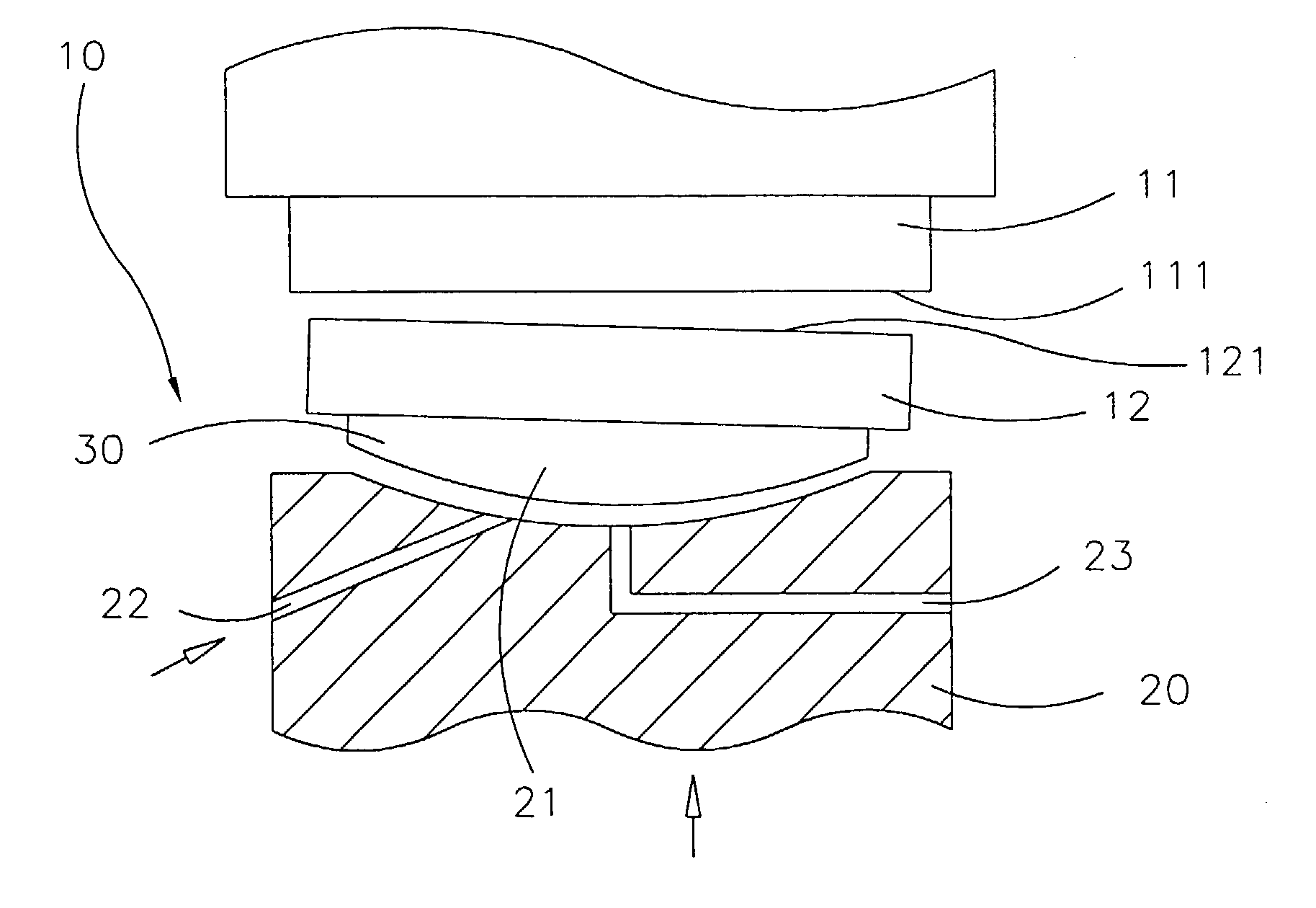
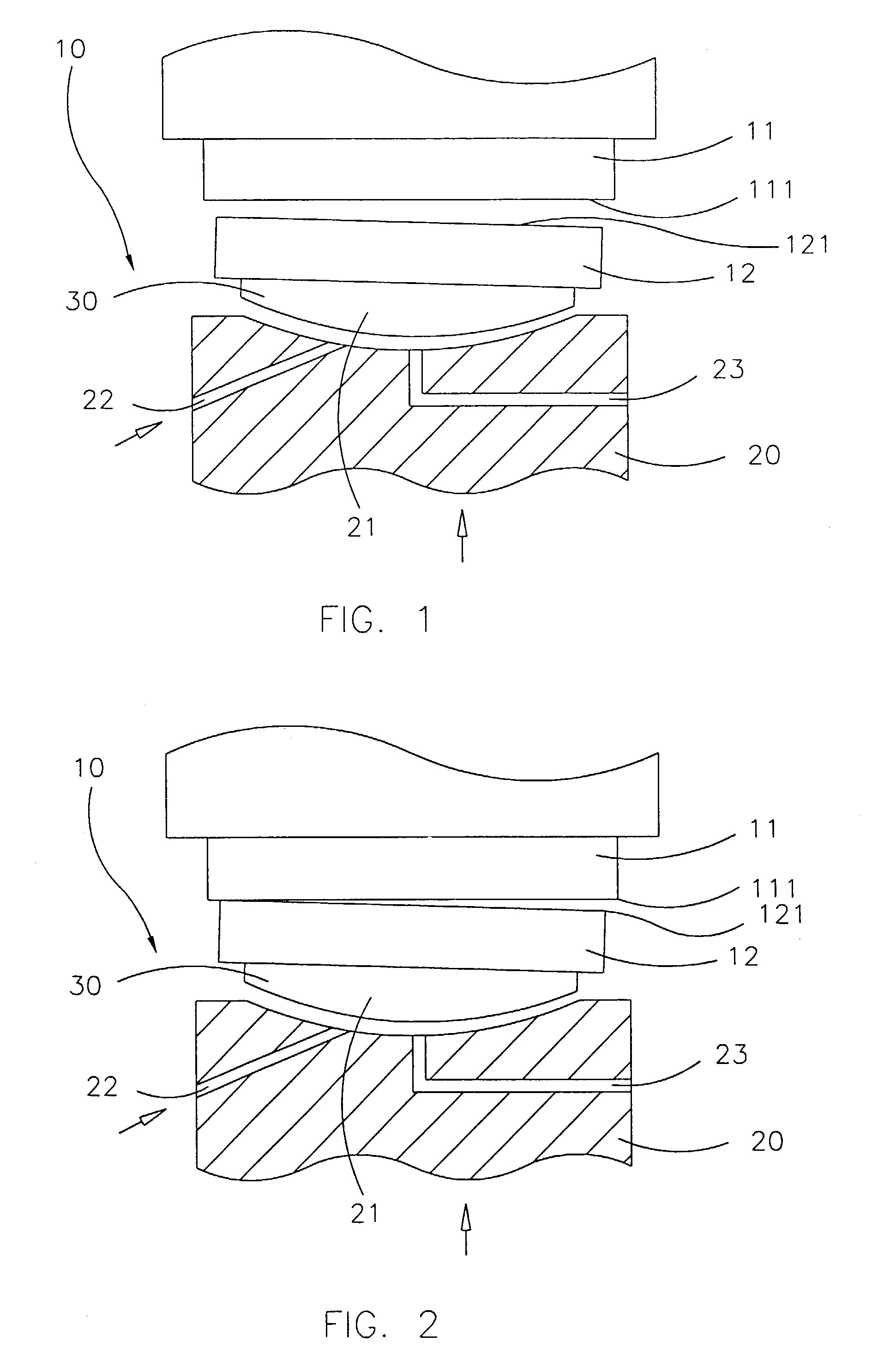
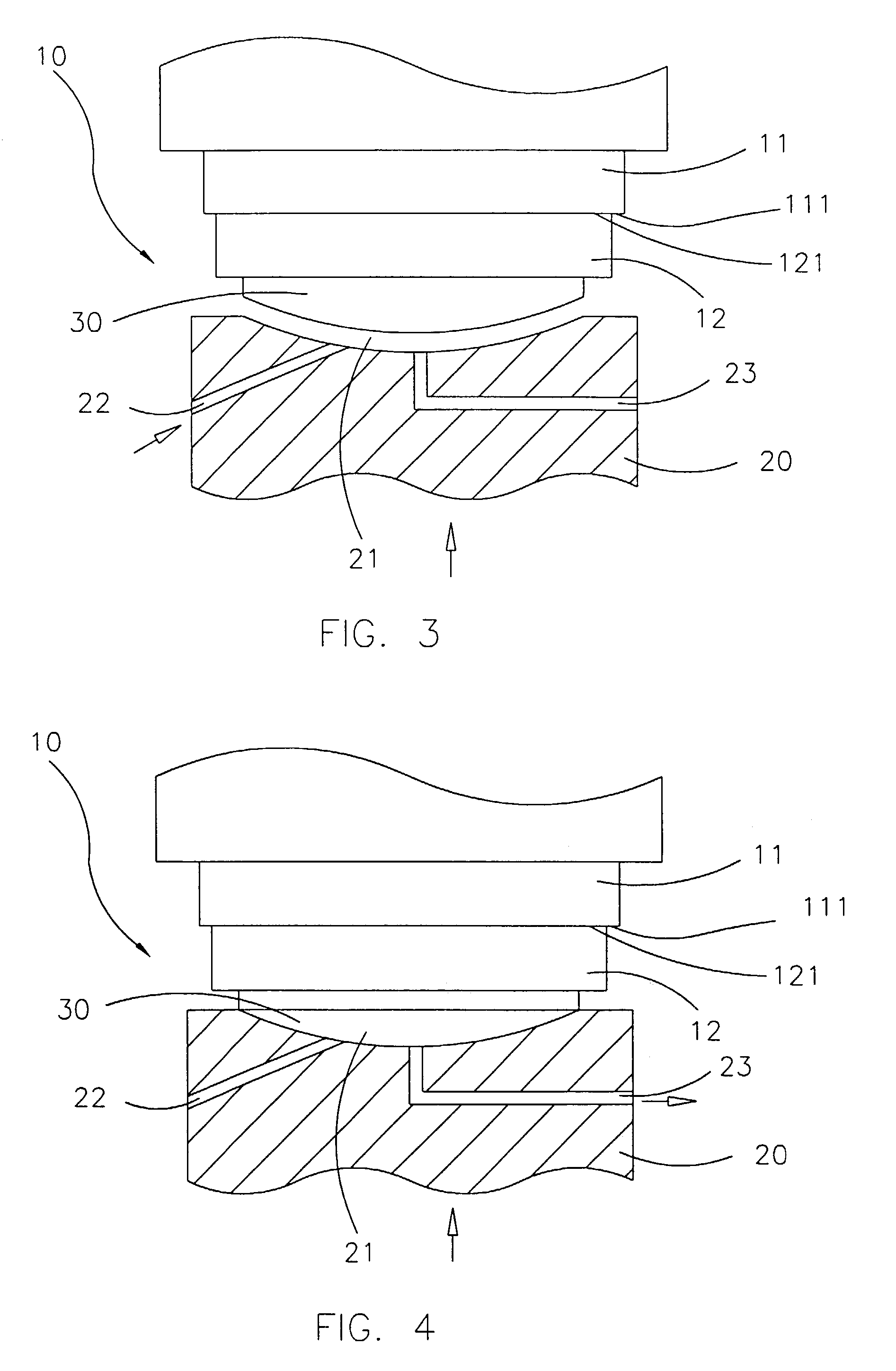
[0008]As shown in FIG. 1, the hot embossing auto-leveling apparatus of the present invention is used in conjunction with a molding machine 10 (e.g., a hot embossing machine) and comprises an upper mold 11 and a lower mold 12 having working surfaces 111, 121, respectively, between which a stamper and a molded part are accommodated. A base 20 supports the lower mold 12. Between the base 20 and the lower mold 12, an upward-acting dual-function spherical bearing 30 is placed. An air inlet 22 is led through the base 20, supplying compressed air, and a vacuum port 23, passing through the base 20, is connected with a vacuum pump for pumping away air.

[0009]Referring to FIGS. 1 and 2, before a molded part is inserted between the upper and lower molds 11, 12 of the molding machine 10, the upper and lower molds 11, 12 perform an upward and downward coupling movement. In this state, when compressed air is led through the air inlet 22 below the dual-function spherical bearing 30, the bearing 30 ...


PUM

PropertyMeasurementUnit
diameteraaaaaaaaaa
diameteraaaaaaaaaa
shapeaaaaaaaaaa

Abstract

A hot embossing auto-leveling apparatus which has an air-floating spherical bearing between a lower mold and a base, placed in a depression on the base, with the base housing an air inlet and an air outlet. A hot embossing auto-leveling method, comprising the steps of (1) performing an upward and downward coupling movement of the lower and upper molds; (2) adjusting the lower mold against the upper mold using the air-floating spherical bearing; (3) fixing the lower mold by under pressure in an orientation parallel to the upper mold; (4) placing a molded part on the lower mold; (5) evacuating, heating and pressurizing a working chamber; (6) cooling; and (7) opening.

Description

FIELD OF THE INVENTION[0001]The present invention relates to a hot embossing auto-leveling apparatus and method, particularly to a dynamic auto-leveling apparatus and method which before every molding step performs a vertical and horizontal leveling movement for maintaining precision and parallelism of upper and lower molds, performing auto-leveling while a relatively good mold is molded against a stamper and high-molecular material, so that the shortcoming of conventional molds which do not allow for controlling alignment and parallelism is avoided.DESCRIPTION OF RELATED ART[0002]When conventional hot embossing is conducted, upper and lower molds in fixed positions are used, fixing alignment and parallelism at the time of installation. With the tendency of molding parts by embossing the dimensions of which are in the range of micrometers or even nanometers, the influence of alignment and parallelism has become significant.[0003]If a mold having a diameter of 150 mm is misaligned by...

Claims


Application Information

Patent Timeline
Patent Type & Authority Patents(United States)
IPC IPC(8): B29C59/02B29C59/00B44B5/00
CPCB29C59/002B44B5/00B29C59/02
Inventor HUANG, JUNG YANTSAI, CHU SHUCHAO, CHOUNG-LIIMU, CHUAN KANGYANG, JAUH JUNGHUANG, CHENG-CHUNLIU, MING YUEH
Owner IND TECH RES INST
Learn More