
Contamination preventive cap

a technology of anti-pollution and protective cap, which is applied in the field of anti-pollution cap, can solve the problems that the aseptic condition of the eyedrops container cannot be secured, and achieve the effect of preventing the pressing member and minimizing the deformation of the first tight contact member

Inactive Publication Date: 2006-10-03
SANTEN PHARMA CO LTD
View PDF15 Cites 28 Cited by
  • Summary
  • Abstract
  • Description
  • Claims
  • Application Information

AI Technical Summary

Benefits of technology

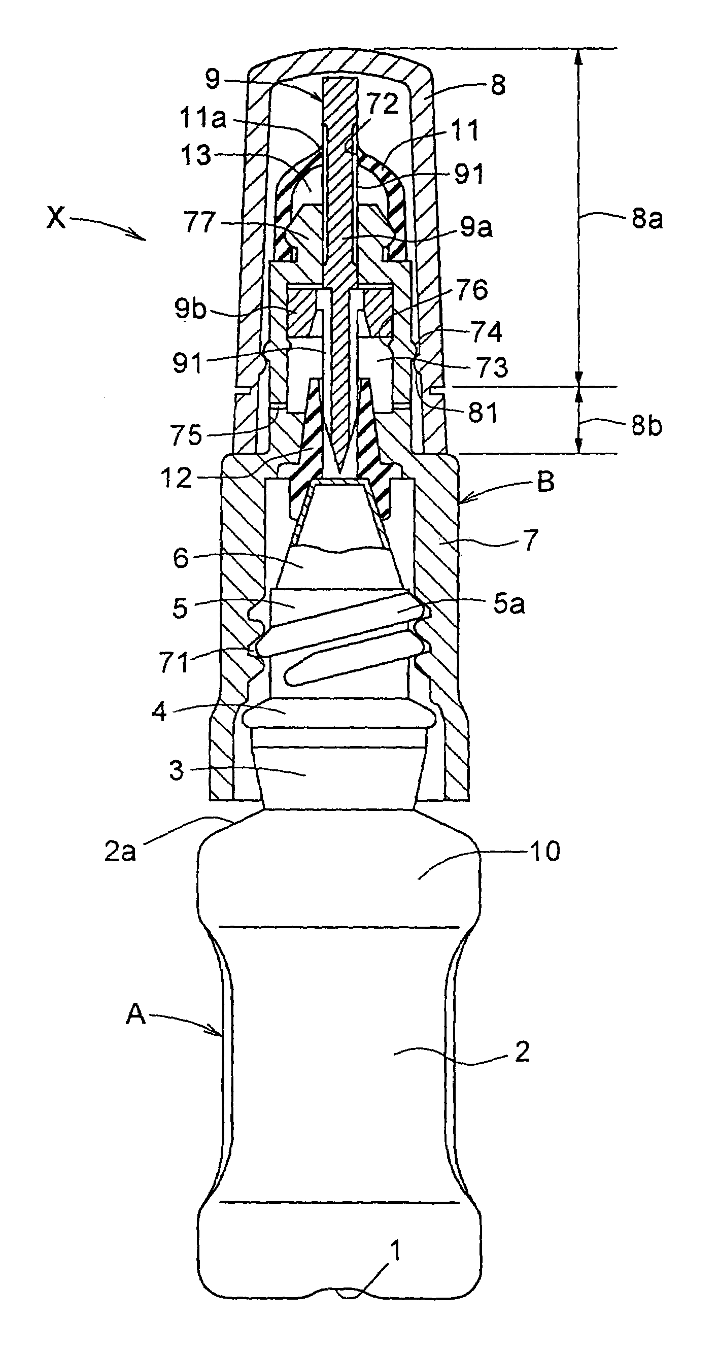
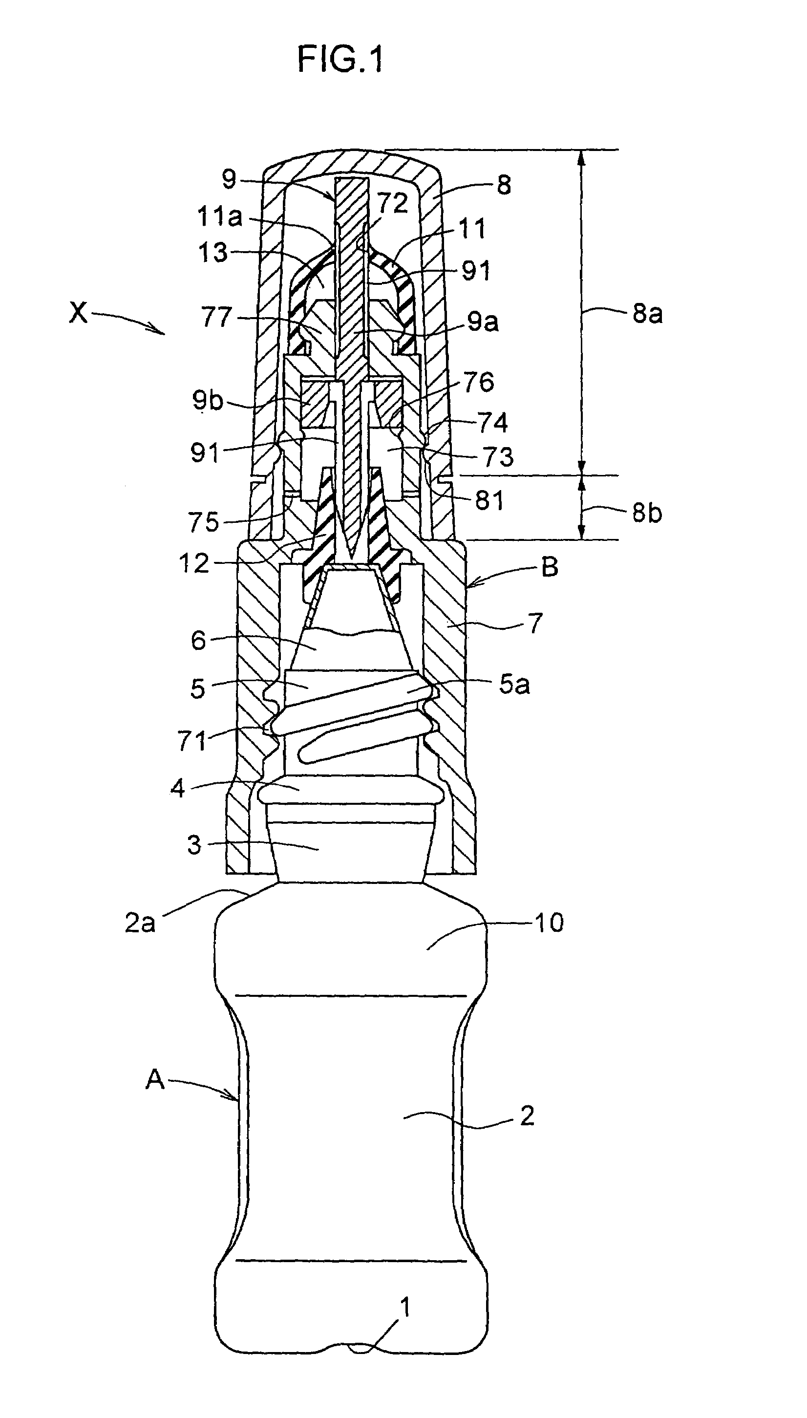
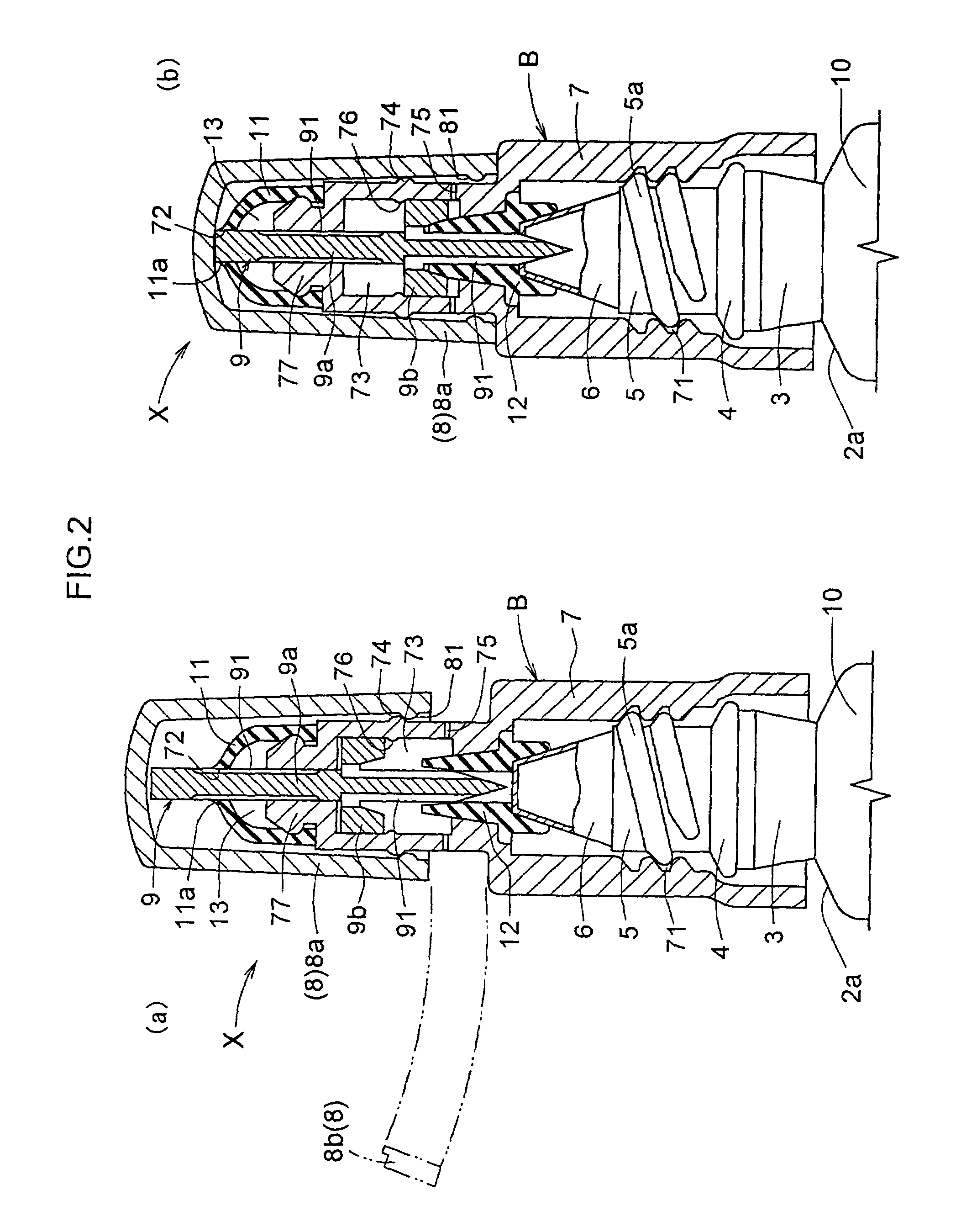
[0012]As illustrated in FIG. 1, the first characteristic feature according to the present invention is that the cap comprises a base member 7 attachable to a main container body 10 for containing a fluid, a overcap 8 mountable on the base member 7, a pressing member 9 inserted into and held by the base member 7 to be slidable relative thereto, with a groove portion 91 formed in a side face thereof for guiding the fluid to the outside, the pressing member being pressed toward the main container body 10 by the overcap 8 to cancel a sealed condition of the main container body 10, a first tight contact member 11 provided on a tip end portion 77 of the base member 7 to be placed in tight contact with the pressing member 9 from outside and yet allow the fluid to be discharged therethrough, and a second tight contact member 12 provided on an inner periphery of the base member 7 to be placed in tight contact with the pressing member 9 in a pressed position thereby preventing the fluid from being discharged therethrough and yet allowing the external air to flow therein.
[0030]Further, since the projections are arranged close to the first tight contact member, the first tight contact member is placed in contact with the projections immediately when the first tight contact member is about to deform toward the base member, thereby to stop movement of the first tight contact member. As a result, deformation of the first tight contact member can be minimized, if any.

Problems solved by technology

At this time, the aseptic condition within the eyedrops container cannot be secured because of germs present in the ambient air or the like, which might pollute the interior of the eyedrops container (interior pollution of the eyedrops container after it is opened).

Method used


Image

  • Contamination preventive cap
  • Contamination preventive cap
  • Contamination preventive cap

Examples


embodiment 1

ALTERNATIVE EMBODIMENT 1

[0090]In the embodiment described above, a filter member 78 may be held by the pressing member 9 and the base member 7 with the pressing member 9 being pressed in (FIG. 6).

[0091]In a use state in which the sealed condition of the eyedrops container is canceled, ambient air flows into the eyedrops container A in a volume corresponding to the medical fluid applied for instillation. The air is taken in from the second communicating aperture 75 to flow into the eyedrops container A through between the pressing member 9 and the base member 7.

[0092]Since the filter member 78 is provided to be held by the pressing member 9 and the base member 7 with the pressing member 9 being pressed in, particles and microorganisms present in the air can be captured by the filter 78, even if the air flows in in the volume corresponding to the medical fluid applied. This prevents the medical fluid contained in the eyedrops container A from being polluted by the air, thereby to effe...

embodiment 2

ALTERNATIVE EMBODIMENT 2

[0095]In the construction described in the above alternative embodiment 1, the base member 7 may include a first base member 7a and a second base member 7b, in which the filter member 78 is fixed at an outer periphery thereof by the first base member 7a and the second base member 7b before the pressing member 9 is pressed in (FIG. 7).

[0096]Thus, the filter member 78 is fixed at the outer periphery thereof by the first base member 7a and the second base member 7b, thereby to stabilize the position of the filter member 78. As a result, the filter member 78 is prevented from being held by the first base member 7a and the second base member 7b in an abnormal position, thereby to reliably perform the filtering function.

[0097]In this case, a gap produced between the first base member 7a and the second base member 7b may serve as the second communicating aperture 75.

embodiment 3

ALTERNATIVE EMBODIMENT 3

[0098]In the embodiments described above, projections 79 may be dispersed on the tip portion 77 of the base member 7 for restraining the first tight contact member 11 from being deformed toward the base member 7 (FIG. 8). The projections 79 are desirably arranged close to the first tight contact member 11 (FIG. 9).

[0099]The first tight contact member 11 may have a possibility of being deformed toward the base member 7 by the friction between the pressing member 9 and the first tight contact member 11 when the pressing member 9 is placed in the pressed position. However, even if the first tight contact member 11 is deformed toward the base member 7, the projections 79 dispersed on the tip end portion of the base member 7 (FIG. 8) are allowed to contact the first tight contact member 11 generally evenly around the tip end portion of the base member 7. Hence, the first tight contact member 11 may be deformed, its irregular distortion hardly occurs. This prevents...


PUM


Abstract

An antipollution cap comprises a base member (7) attachable to an eyedrops container (A) for containing a fluid, a overcap (8) mountable on the base member (7), a pressing member (9) inserted into and held by the base member (7) to be slidable relative thereto, with a groove portion (91) formed in a side face thereof for guiding the fluid to the outside, the pressing member being pressed toward the eyedrops container (A) by the overcap (8) to cancel a sealed condition of the eyedrops container (A), a first tight contact member (11) provided on a tip end portion (77) of the base member (7) to be placed in tight contact with the pressing member (9) from outside and yet allow the fluid to be discharged therethrough, and a second tight contact member (12) provided on an inner periphery of the base member (7) to be placed in tight contact with the pressing member (9) in a pressed position thereby preventing the fluid from being discharged therethrough and yet allowing ambient air to flow therein.

Description

TECHNICAL FIELD[0001]This invention relates to an antipollution cap mounted on a medical eyedrops container (hereinafter simply called “eyedrops container”) for containing medical eyedrops for instillation.BACKGROUND ART[0002]Examples of existing eyedropper, especially those for applying a medical fluid such as medical eyedrops, which are in wide use, are what is called a three-piece type eyedropper including a main container body in the form of a hollow cylinder, with an instilling tube attached thereto, and with a cap mounted on the main container body to make three components forming a whole eyedropper, and, as shown in FIG. 11, what is called a bottle pack eyedropper X which may be an integral molding type container A, with an instilling tube 6 and a main container body 10 formed integrally by blow molding or vacuum forming technique, and with a cap B screwed or fitted to the container A. It is also known that the instilling tube 6 has a stopper with an instilling opening 6a mou...

Claims


Application Information

Patent Timeline
Patent Type & Authority Patents(United States)
IPC IPC(8): B67D5/00B67D99/00A61J1/00A61J1/14B65D51/22
CPCA61J1/1412A61J1/18B65D51/227A61J1/1406A61J2001/1418A61J2001/145A61J2001/1468A61J2001/201A61J2001/2065A61J2001/2075A61J2001/2082B65D2101/0038B65D2251/0015B65D2251/0056B65D2251/0096A61J1/201A61J1/2065A61J1/2075A61J1/1418A61J1/1468A61J1/2082A61J1/145B65D2401/25
Inventor YAMADA, HIROSHI
Owner SANTEN PHARMA CO LTD
Learn More