
Integral insert molded fiber optic transceiver electromagnetic interference shield

a technology of electromagnetic interference shield and insert, which is applied in the direction of coupling device connection, instruments, other domestic objects, etc., can solve the problems of low mechanical strength, interference with other electronic equipment, and molded plastic transceiver housings

Active Publication Date: 2006-09-26
AVAGO TECH INT SALES PTE LTD
View PDF16 Cites 30 Cited by
  • Summary
  • Abstract
  • Description
  • Claims
  • Application Information

AI Technical Summary

Benefits of technology

The invention is a fiber optic module that includes a housing with an EMI shield. The module has an optoelectronic subassembly mounted inside the housing and a second housing that encloses the subassembly. The EMI shield is made of a conductive mesh and fingers. The housing is made of a non-conductive material, and the floor and sidewalls are molded through the mesh of the shield to make contact with ground. The technical effect of this invention is that it provides better protection against electromagnetic interference, which can improve the performance and reliability of the fiber optic module.

Problems solved by technology

Excessive EMI emission causes interference with other electronic equipment.
The disadvantages of injection molded plastic transceiver housings include relatively low mechanical strength and poor EMI performance (since the plastic is electromagnetically transparent, allowing EMI to escape from the transceiver module thru the bezel opening).
Metal housings are more costly than plastic housings, and often require fasteners to assemble because snap-together features are difficult to design in metal.
These fasteners add additional material and labor cost.
However, metal doors add to the overall cost of the equipment, inhibit access for service, and hamper fiber routing.
However, this requires perforation of the housing resulting in a dramatically reduced housing cross-section where the shield is inserted.
The reduced cross-section decreases the strength of the housing under bending, resulting in breakage of the housing when fiber optic connector is subject to side loading (i.e., forces applied to the fiber acting perpendicular to the long axis of the transceiver).
However, metallization is expensive and may flake off and contaminate the optics in the transceiver.

Method used


Image

  • Integral insert molded fiber optic transceiver electromagnetic interference shield
  • Integral insert molded fiber optic transceiver electromagnetic interference shield
  • Integral insert molded fiber optic transceiver electromagnetic interference shield

Examples


Embodiment Construction

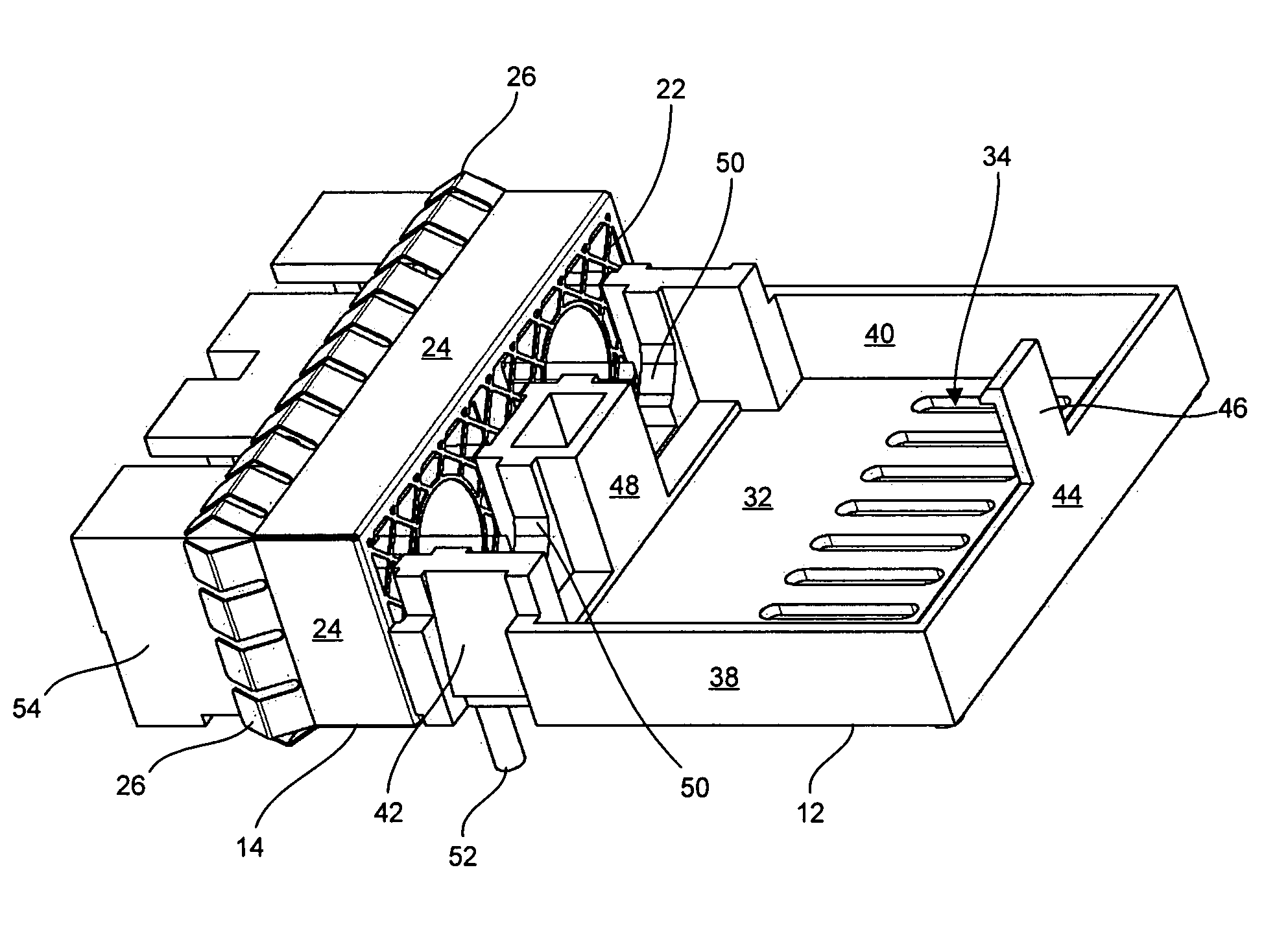
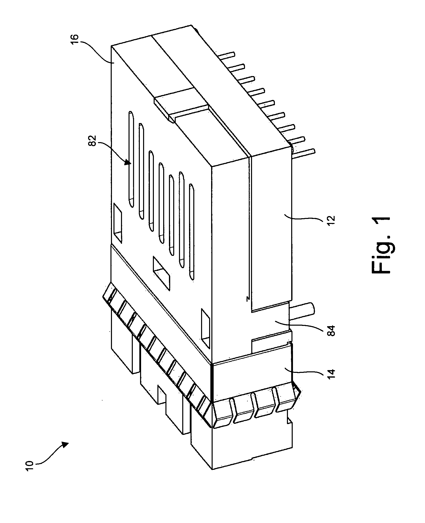
[0015]FIG. 1 illustrates a fiber optic module 10 in one embodiment of the invention. Fiber optic module 10 can be a transmitter, a receiver, or a transceiver of any form factor, such as a SFF (Small Form-Factor), SFP (Small Form-factor Pluggable), GBIC (Gigabit Interface Converter), 1×9, or MTRJ (Multifiber in the Telecom RJ form factor) transceiver. Fiber optic module 10 includes a lower housing 12 insert molded with an electromagnetic interference (EMI) shield 14, and an upper housing 16 mounted atop lower housing 12 secured by cantilever hooks 84.

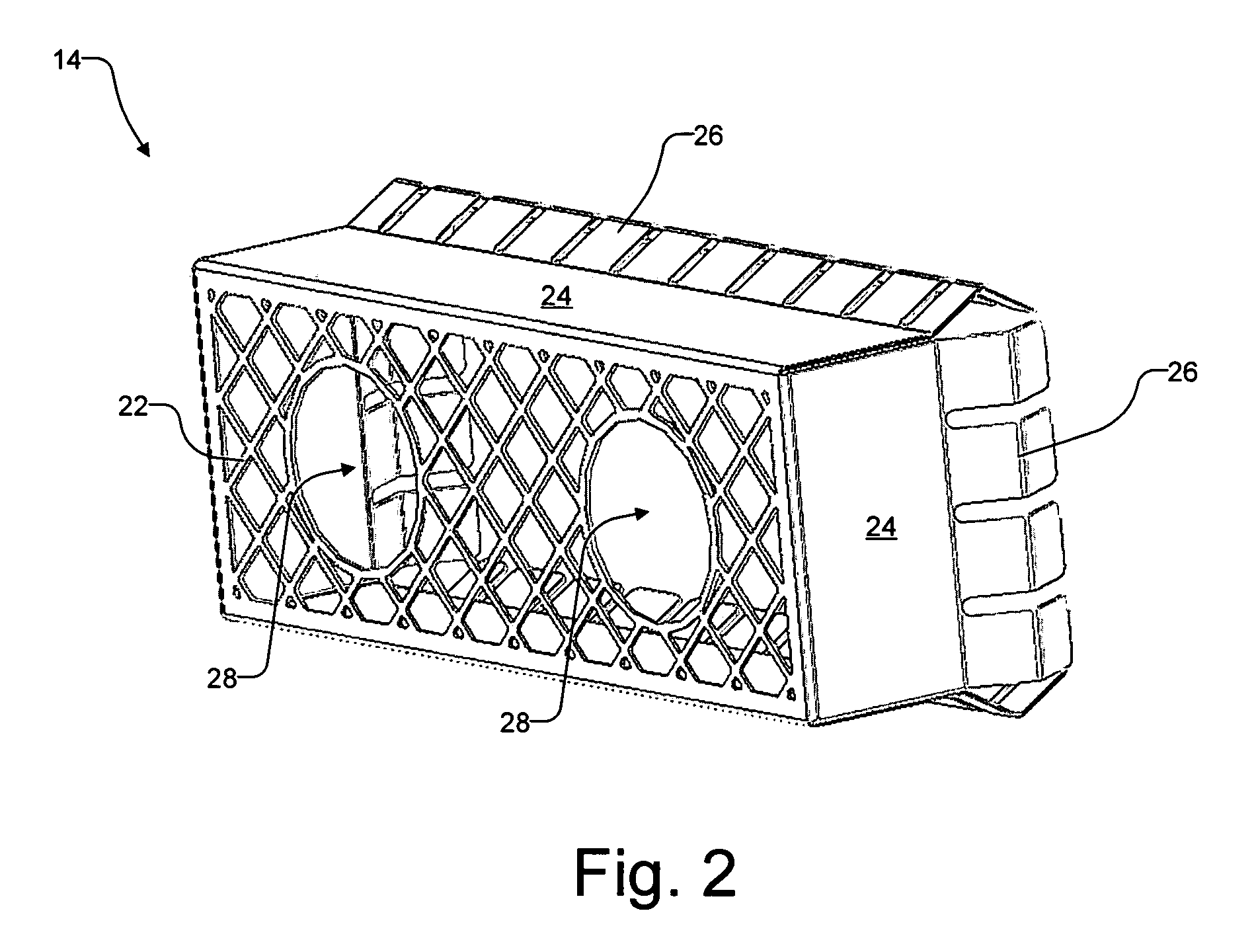
[0016]FIG. 2 illustrates EMI shield 14 separate from lower housing 12 in one embodiment of the invention. EMI shield 14 includes an electrically conductive mesh 22, electrically conductive shield sidewalls 24 around mesh 22, and electrically conductive contact fingers 26 (not all labeled) extending from shield sidewalls 24. Mesh 22 has small perforations that shield EMI over the frequency range of interest from escaping through a nose 54...


PUM

PropertyMeasurementUnit
conductiveaaaaaaaaaa
perimeteraaaaaaaaaa
non-conductiveaaaaaaaaaa

Abstract

A fiber optic module includes a first housing insert molded with an electromagnetic interference (EMI) shield, an optoelectronic subassembly mounted in the first housing, and a second housing mounted to the first housing to enclose the optoelectronic subassembly. The EMI shield includes a conductive mesh and conductive contact fingers. The first housing includes a non-conductive housing floor, non-conductive housing sidewalls, and a non-conductive nose defining at least one connector receptacle, wherein the housing floor and the housing sidewalls are injection molded through the mesh of the EMI shield to be integral with the nose and so that the fingers at least partially surround the nose.

Description

DESCRIPTION OF RELATED ART[0001]As communication bit rates and fiber optic transceiver densities in networking equipment increase, more EMI (electromagnetic interference) is radiated from the optical ports. Excessive EMI emission causes interference with other electronic equipment.[0002]Low fiber optic transceiver cost is achieved by using injection molded plastic parts whenever possible. In addition to having low material and fabrication costs, injection molded plastic parts enable snap-fit assemblies, further decreasing the cost of the transceiver by eliminating fasteners and assembly labor. The disadvantages of injection molded plastic transceiver housings include relatively low mechanical strength and poor EMI performance (since the plastic is electromagnetically transparent, allowing EMI to escape from the transceiver module thru the bezel opening).[0003]One prior art solution uses external sheet metal shields on fiber optic transceivers. However, only the perimeter is shielded...

Claims


Application Information

Patent Timeline
Patent Type & Authority Patents(United States)
IPC IPC(8): G02B6/36B29D11/00G02B6/00G02B6/10H05K9/00G02B6/42G02B6/12H01R13/658
CPCG02B6/4201H05K9/0058G02B6/4277G02B6/4246H01R13/659H01R13/6582
Inventor SCHWIEBERT, MATTHEW K.MURPHY, R. SEAN
Owner AVAGO TECH INT SALES PTE LTD
Learn More