
Engine control to compensate for fueling dynamics

a fuel injection compensation and engine technology, applied in electrical control, machines/engines, non-mechanical valves, etc., can solve the problems of inability to accurately control the air-fuel ratio of the active cylinder, not all injected fuel enters the combustion chamber, and errors can occur, etc., to achieve more accurate air-fuel ratio control, more accurate fueling to the active cylinder, and more accurate fueling

Active Publication Date: 2006-09-26
FORD GLOBAL TECH LLC
View PDF16 Cites 46 Cited by
  • Summary
  • Abstract
  • Description
  • Claims
  • Application Information

AI Technical Summary

Benefits of technology

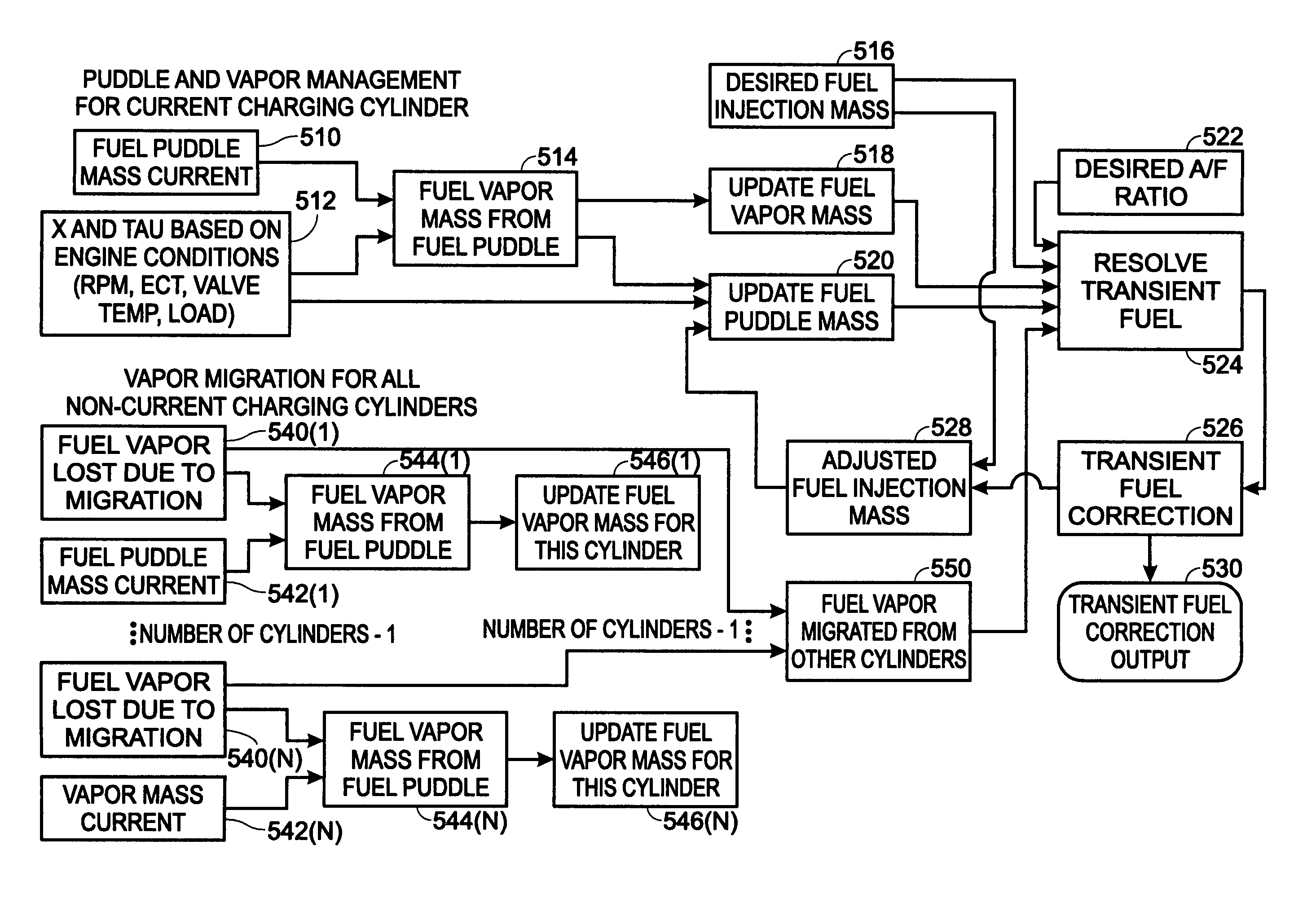
[0007]In this way, it is possible to separate the fuel puddle and vapor migration between firing, and non-firing cylinders. This allows for compensation of the effects of cylinder valve deactivation, including vapor migration from deactivated cylinders to active cylinders, and thus more accurate air-fuel ratio control.
[0010]Thus, by considering fuel evaporating from a puddle of another deactivated cylinder, it is possible to provide more accurate fueling to active cylinders, thus providing more accurate air-fuel ratio control. In another embodiment, by tracking and updating vapor fuel mass and puddle fuel mass at each combustion event to maintain the latest status for vapor fuel and puddle fuel at each cylinder, or intake port, it is also possible to provide more accurate fueling to active cylinders.

Problems solved by technology

However, not all injected fuel enters the combustion chamber.
The inventors herein have recognized a disadvantage with such approaches.
Specifically, although the compensation is performed on an individual cylinder basis, if used for cylinders with deactivated cylinder valves, or cylinders operating in a variety of number of strokes, errors can occur.
Specifically, even though cylinder valves may be deactivated, fuel vapors can still leave the fuel puddles and migrate to other cylinders, thereby affecting the inducted air-fuel ratio.

Method used


Image

  • Engine control to compensate for fueling dynamics
  • Engine control to compensate for fueling dynamics
  • Engine control to compensate for fueling dynamics

Examples


Embodiment Construction

)

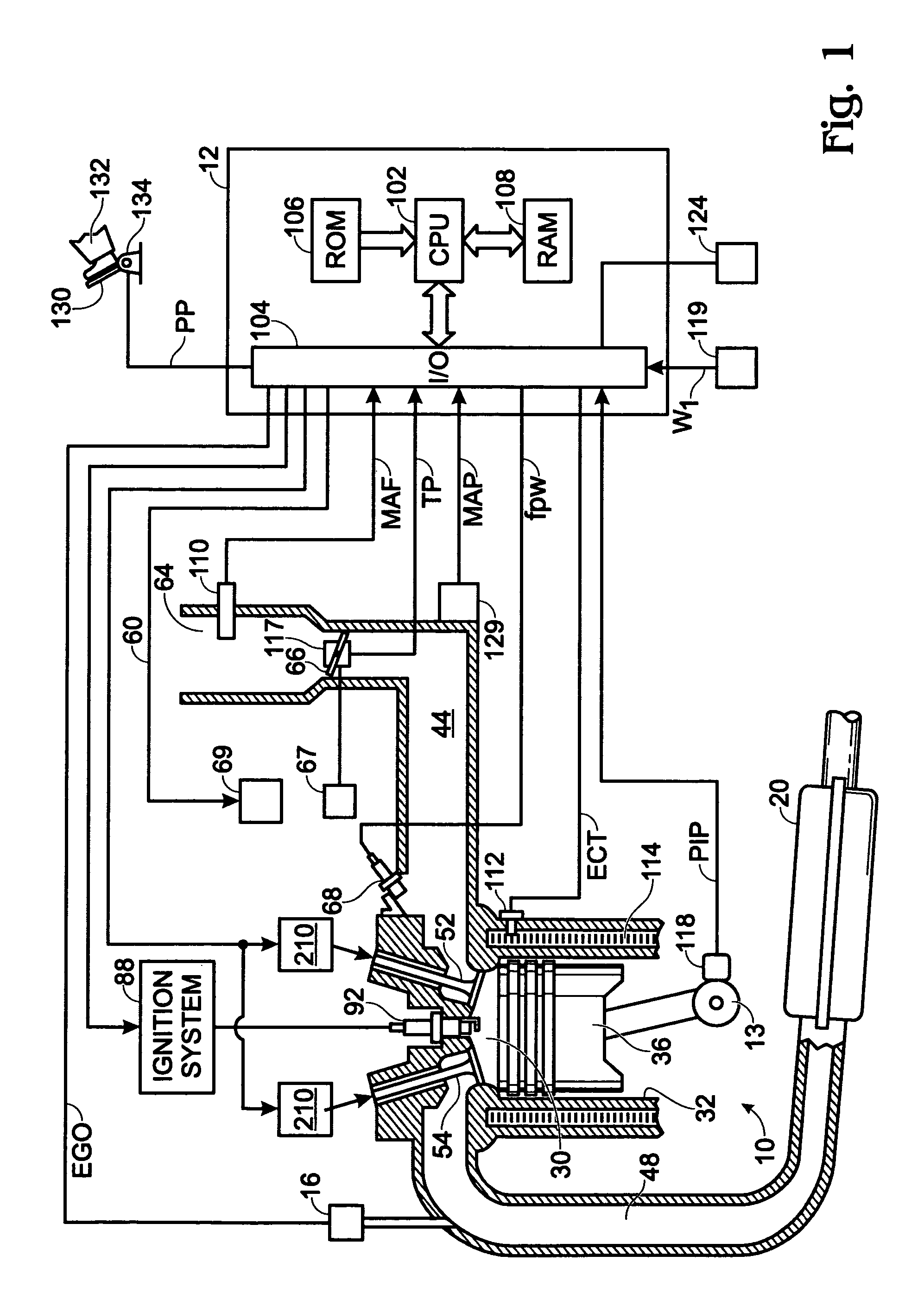
[0020]Referring to FIG. 1, internal combustion engine 10 is shown. Engine 10 is an engine of a passenger vehicle or truck driven on roads by drivers. Engine 10 is coupled to torque converter via crankshaft 13. The torque converter is also coupled to transmission via turbine shaft. The torque converter has a bypass clutch which can be engaged, disengaged, or partially engaged. When the clutch is either disengaged or partially engaged, the torque converter is said to be in an unlocked state. The turbine shaft is also known as transmission input shaft. The transmission comprises an electronically controlled transmission with a plurality of selectable discrete gear ratios. The transmission also comprises various other gears such as, for example, a final drive ratio. The transmission is also coupled to tires via an axle. The tires interface the vehicle to the road.

[0021]Internal combustion engine 10 comprising a plurality of cylinders, one cylinder of which, shown in FIG. 1, is controll...


PUM


Abstract

A method for calculating transient fuel wall wetting characteristics of an operating engine is described. The method accounts for cylinder valve deactivation of cylinders in the engine in calculating the dynamic fueling compensation. In one example, fuel vaporization effects from fuel puddles in deactivated cylinders is considered when calculating the fueling compensation for active cylinders.

Description

TECHNICAL FIELD[0001]The field of the invention relates to internal combustion engine fuel injection compensation for fueling dynamics, wherein the fueling dynamics are variable between cylinders and the engine operates in various combustion modes depending on electric valve operation.BACKGROUND OF THE INVENTION[0002]Internal combustion engines are controlled to maintain a desired air to fuel ratio in the combustion chamber to reduce emissions. Fuel is delivered via electronically controlled fuel injectors, modernly located in intake parts of the engine's cylinders, for example. However, not all injected fuel enters the combustion chamber. Rather, some fuel is stored in the intake manifold of the engine. This phenomenon is known as “wall wetting” and various approaches are available for taking into account the fuel puddles in the intake manifold in controlling engine air fuel ratio.[0003]Individual cylinder compensation can also be used to develop an individual cylinder wall wetting...

Claims


Application Information

Patent Timeline
Patent Type & Authority Patents(United States)
IPC IPC(8): F02B75/02F01L9/20F02D13/06F02D17/02F02D41/00F02D41/04F02D41/32F02D41/36
CPCF01L9/04F02D17/02F02D41/0087F02D41/047F02D13/06F01L13/0005F01L2009/0436F01L2800/00F02B2275/16Y02T10/18F02D2041/0012Y02T10/123Y02T10/12F01L2009/2136F01L9/20
Inventor SONG, GANGKOLMANOVSKY, ILYA V.MICHELINI, JOHN OTTAVIOLEWIS, DONALD J.
Owner FORD GLOBAL TECH LLC
Learn More