
Beamformer for multi-beam broadcast antenna

a beamformer and antenna technology, applied in diversity/multi-antenna systems, individual energised antenna arrays, wireless communication, etc., can solve the problems of prohibitively expensive and unwieldy application of this technology to a typical mobile telephone system, and reducing the number of phase and gain control devices. , to achieve the effect of replacing the multiplicity of antenna hardware and data modulators, less antenna and data communication hardware, and avoiding interferen

Inactive Publication Date: 2006-09-19
EMS TECHNOLOGIES
View PDF27 Cites 57 Cited by
  • Summary
  • Abstract
  • Description
  • Claims
  • Application Information

AI Technical Summary

Benefits of technology

"The present invention is a phased array data communication system that uses an intelligent beam former to broadcast multiple data-containing beams using a single programmable phase and gain control device for each antenna element. The system encodes each beam with the data for the corresponding users by generating a control signal for each antenna element, which includes a total gain and a total phase shift. The control signal is then broadcasted to deliver the data to the users. The system can be manufactured or upgraded without substantially increasing the cost, complexity, size, or weight of the system. The system can also change the selected antenna, beam set, and code set on demand to avoid interference or implement other objectives. The system assigns multiple users to each beam and encodes each beam with the data for the corresponding users by computing the total gain and phase shift for each antenna element. The invention allows for a wide range of phased array antenna systems to be manufactured or upgraded without substantially increasing the cost, complexity, size, or weight of the system."

Problems solved by technology

However, applying this technology to a typical mobile telephone system would be prohibitively expensive and unwieldy.
This approach would require 300,000 phase and gain devices and 10,000 data modulators, which would result in a system that is exorbitantly expensive, complex to construct, large in size, and heavy.
Any one or more of these penalties may be critical for a particular application.
Although the number of phase and gain control devices is greatly reduced, this type of system would still require a very large number of data communication hardware components, including 10,000 data modulators.

Method used


Image

  • Beamformer for multi-beam broadcast antenna
  • Beamformer for multi-beam broadcast antenna
  • Beamformer for multi-beam broadcast antenna

Examples


Embodiment Construction

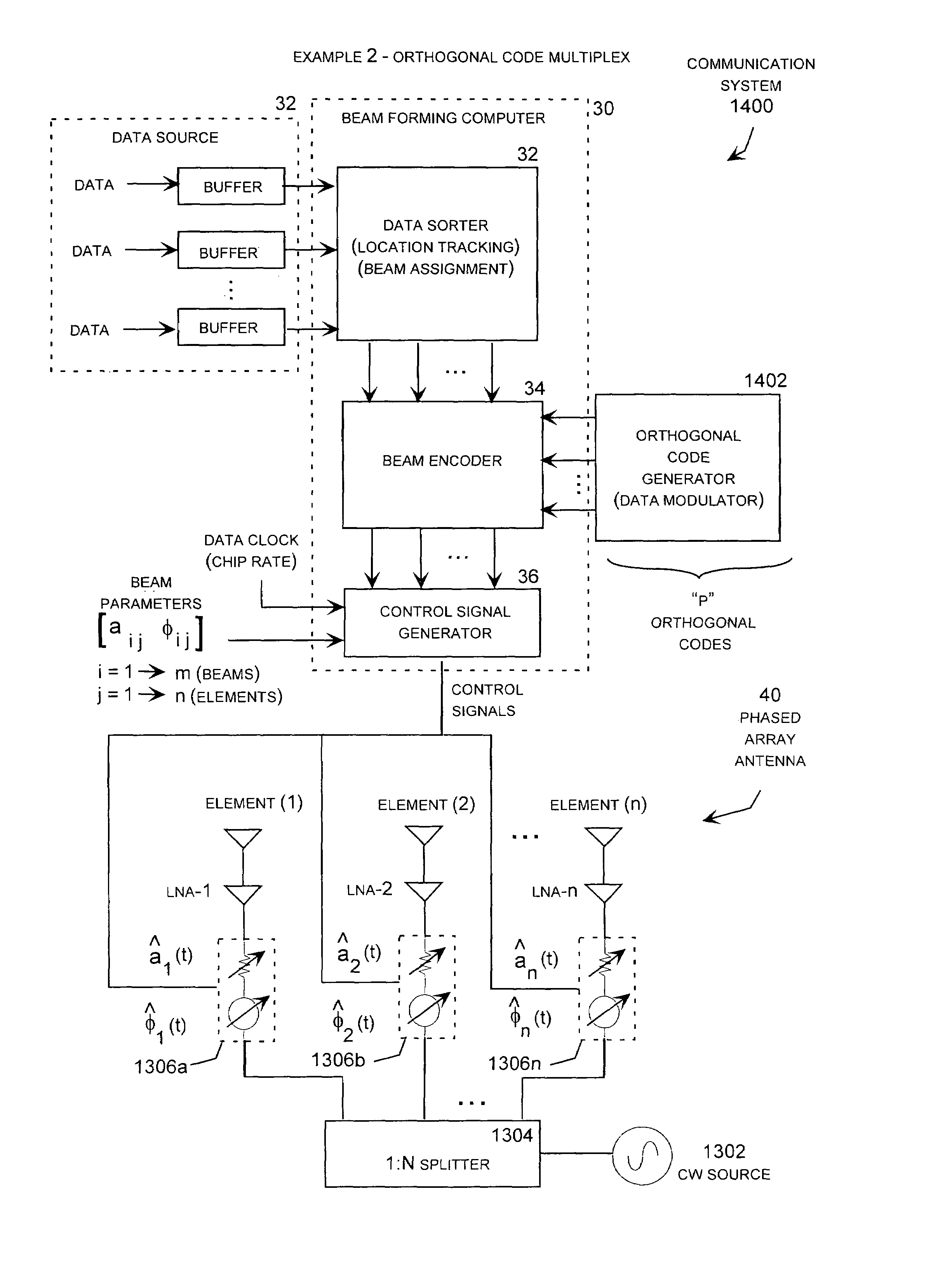
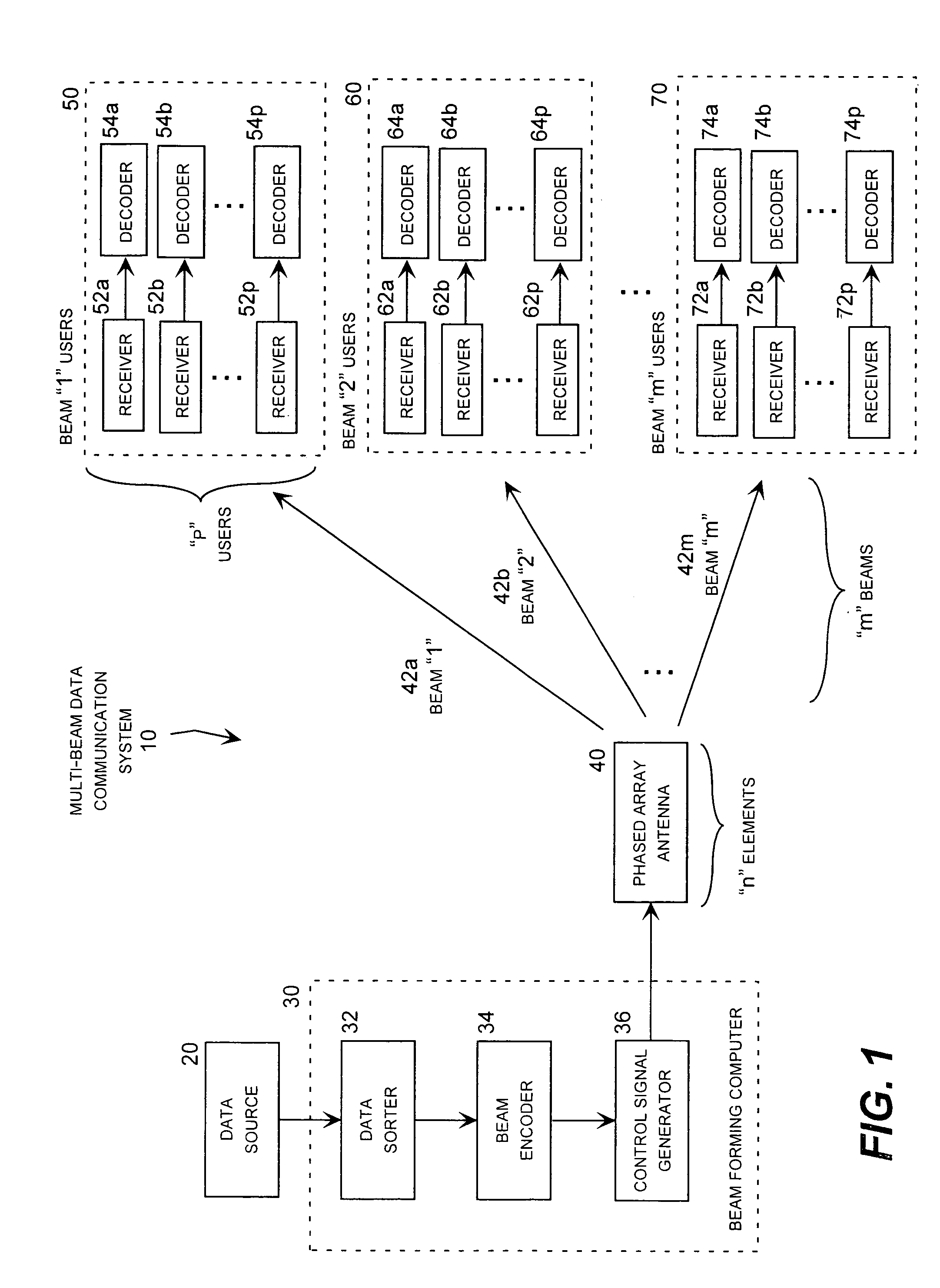
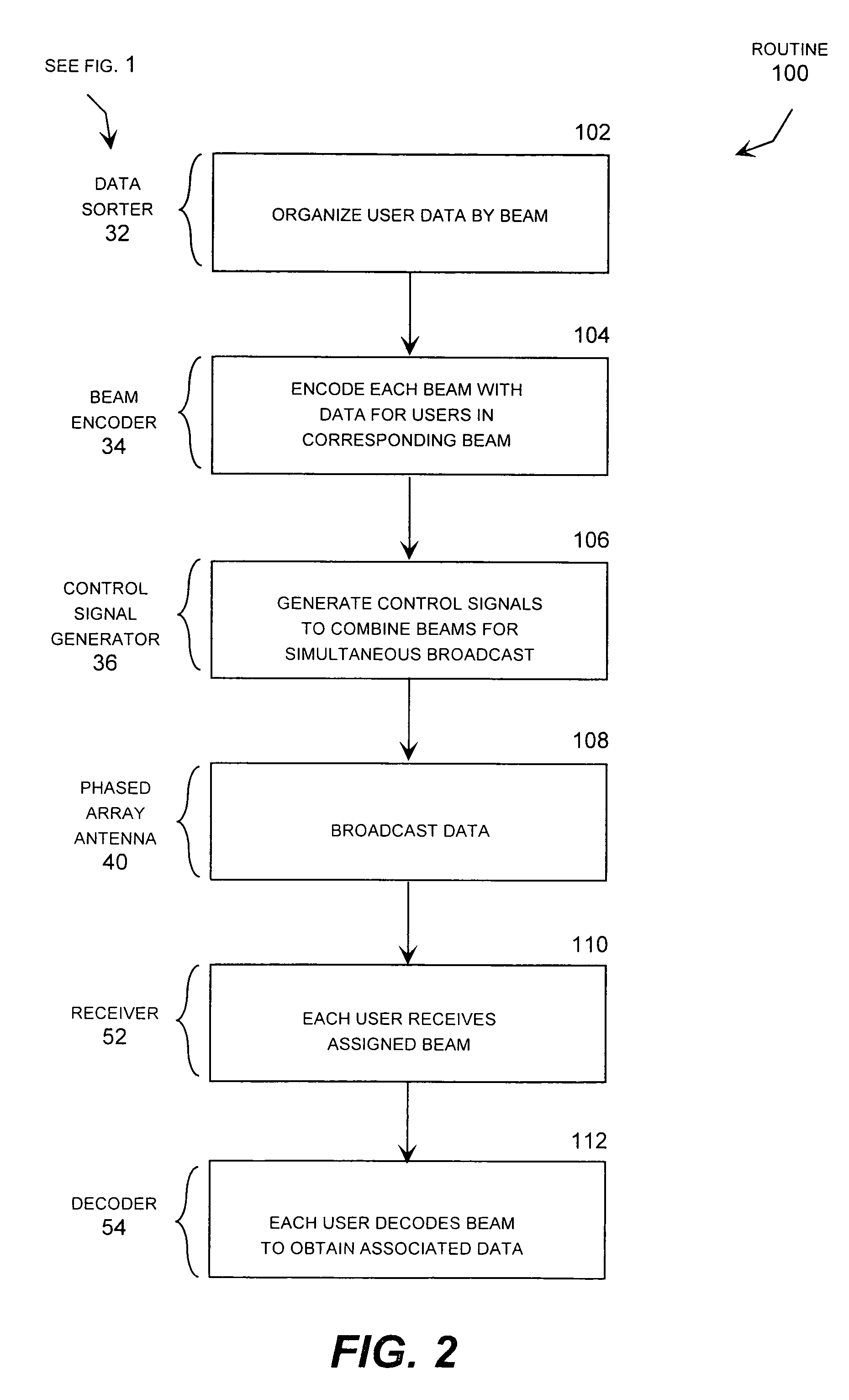
[0041]Briefly described, the invention may be embodied in a phased array data communication system that is operative to simultaneously generate multiple beams that each carry data directed to multiple users located within the corresponding beam. In particular, the phased array antenna may transmit multiple beams in which multiple users are multiplexed into each beam, and each beam is encoded with unique data for multiple users. This allows each beam to include unique data for multiple users located within a transmission coverage area associated with the corresponding beam. An appropriate receiver then receives the beam containing the corresponding user's data using an appropriate filter, and decodes the received beam to extract the data directed to the corresponding user using an appropriate decoder.

[0042]Using this encoding technique, multiple beams that each contain unique data directed to multiple users can be formed with a single set of antenna hardware for each antenna element ...


PUM


Abstract

A phased array antenna system operative to broadcast multiple beams that each include coded data for specific users located within the coverage area of the corresponding beam. An appropriate receiver then receives and decodes a particular beam to extract the specific data for a corresponding user. Multiple users may be assigned to each beam using frequency division or orthogonal code multiplexing, and the user data may be encoded into the beams using frequency shift key or phase shift key encoding. For each coding technique, the encoded antenna control signals are combined into a total gain and total phase shift control signal, which drives a single phase and gain control device for each antenna element. In addition, a single data modulator generates the coding parameters for the entire communication system.

Description

CROSS-REFERENCE TO RELATED APPLICATIONS[0001]This application claims priority to commonly-owned U.S. Provisional Patent Application Ser. No. 60 / 344,634 entitled “Virtual Beamformer For Communication Applications” filed Nov. 9, 2001.TECHNICAL FIELD[0002]The present invention relates to phased array antenna broadcast systems, such as those used for mobile telephone and other data communication systems, and more particularly relates to a beam former that generates encoded control signals that drive the antenna elements of a phased array to transmit multiple beams that each carry unique data directed to multiple users receiving the corresponding beam.BACKGROUND OF THE INVENTION[0003]Phased array antenna broadcast systems, such as those used for mobile telephone and other data communication systems, take advantage of the phase differential that occurs according to the direction of coherent propagating energy. For example, in a simple array of two closely spaced antenna elements lying in ...

Claims


Application Information

Patent Timeline
Patent Type & Authority Patents(United States)
IPC IPC(8): H01Q3/24H04Q7/20H04Q7/30H01Q3/26H01Q21/06H01Q25/00H04B7/04
CPCH01Q3/26H04B7/0408H01Q25/00H01Q21/061
Inventor HOWELL, JAMES M.
Owner EMS TECHNOLOGIES
Learn More