
Method for converting joystick deflection into motion in a computer vision system

Active Publication Date: 2006-09-12
MITUTOYO CORP
View PDF8 Cites 7 Cited by
  • Summary
  • Abstract
  • Description
  • Claims
  • Application Information

AI Technical Summary

Benefits of technology

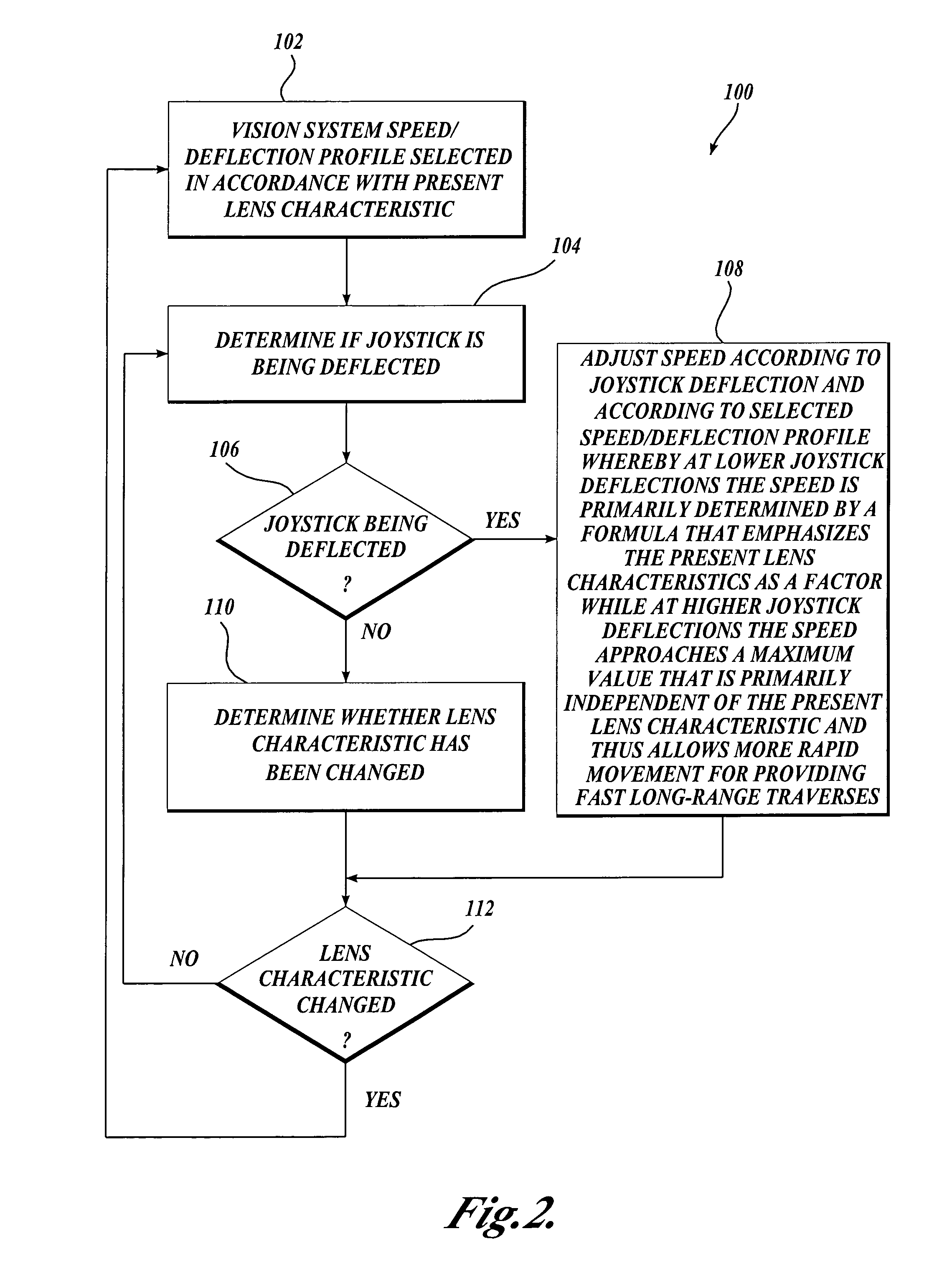
[0007]A method for converting joystick deflection into motion in a computer vision system is provided. In accordance with one aspect of the invention, the conversion of joystick deflection into speed is done according to a speed / deflection profile that is selected in accordance with a current lens characteristic of the system, such as a magnification ratio and / or a depth of field, or any other appropriate lens parameter or combination of parameters indicative of an observable imaging property of the lens. In one embodiment, the speed / deflection profiles are designed so that at lower deflection ranges the speed / deflection profiles are at least partially based on a formula that includes the present lens characteristic as a factor, while at higher deflection ranges, the speed / deflection profiles are designed to become primarily independent of the lens characteristic, and thus allow for fast long-range movement regardless of the present lens characteristic. The speed / deflection profiles may generally be non-linear in nature and the relationship between different speed / deflection profiles may generally be non-linear in nature.
[0009]In accordance with another aspect of the invention, for higher ranges of joystick deflection, the speed / deflection profiles may approach a common transport speed, which is the maximum speed for navigating the stage of the vision system. For machines that can operate in an automatic mode, for example under computer program control, the transport speed may be different depending on whether the manual or automatic control mode is being used. The transport speed of the automatic control mode may be higher than that of the manual control mode, in that the automatic control mode is generally less likely to drive the stage in a manner that could cause damage to the system.
[0010]It will be appreciated that the disclosed method for converting joystick deflection into motion is advantageous in that the system factors in lens characteristics such as magnification and / or depth of field at small joystick deflections which typically occur during ostensible precision maneuvers, and also is able to move rapidly (for providing fast long-range traverses) for large joystick deflections. It will also be appreciated that in various exemplary embodiments the disclosed method is advantageous in that the method provides an intuitive and consistent ergonomic feel in relation to a video display of the image seen by the vision system camera, regardless of the lens in use.

Problems solved by technology

Furthermore, for short working distance lenses, there is a significant risk that the user may accidentally cause the lens to collide with the work piece during a Z-axis motion.

Method used


Image

  • Method for converting joystick deflection into motion in a computer vision system
  • Method for converting joystick deflection into motion in a computer vision system
  • Method for converting joystick deflection into motion in a computer vision system

Examples


Embodiment Construction

[0023]FIG. 1 is a block diagram of one exemplary vision system 10 in accordance with the present invention. Vision system 10 includes a vision measuring machine 12 that is operably connected to exchange data and control signals with a controlling computer system 14. The controlling computer system 14 is further operably connected to exchange data and control signals with a monitor 16, a printer 18, a joystick 22, a keyboard 24, and a mouse 26. The vision measuring machine 12 includes a moveable workpiece stage 32 and an optical imaging system 34 which includes interchangeable lenses. The interchangeable lenses generally provide various magnifications for the images provided by the optical imaging system 34.

[0024]In various exemplary embodiments the optical imaging system 34 includes a zoom lens system that provides the functional equivalent of a variety of interchangeable lenses. It should be appreciated that for a zoom lens systems, the magnification may be varied continuously. Gen...


PUM


Abstract

A method is provided for converting joystick deflection into a speed of relative motion between a image system and a workpiece stage in a computer vision system. The conversion of joystick deflection into speed may be described in terms of a speed / deflection profile that corresponds a present lens characteristics of the system. In one embodiment, the speed / deflection response of the system depends relatively strongly on the present lens characteristic at relatively lower deflections and depends on relatively weakly on the present lens characteristic as the deflection approaches a maximum deflection. The system is advantageous in that, for any lens used, it maintains consistent ergonomic and visual feel at small joystick deflections which typically occur during ostensible precision maneuvers, but is also able to provide fast long-range traverses for large joystick deflections.

Description

FIELD OF THE INVENTION[0001]The invention relates generally to methods for operating a computer vision system to scan and measure an object, and more particularly to a method for converting deflection of a joystick or other manual control device into motion in a computer vision system.BACKGROUND OF THE INVENTION[0002]Computer vision systems can be utilized to obtain precise dimensional measurements of inspected objects. Such systems may include a computer and a camera and optical system with a stage that is movable to allow the camera to scan the surface of an object that is being inspected. One exemplary prior art system that is commercially available is the QUICK VISION™ series of vision inspection machines and QVPAK™ software available from Mitutoyo America Corporation (MAC), located in Aurora, Ill. This product is able to provide images of an object at various magnifications, and move the stage as necessary to traverse the object surface beyond the limits of any single video ima...

Claims


Application Information

Patent Timeline
IPC IPC(8): G09G5/08G05B1/06G05G9/047G09G5/00
CPCG02B21/365G01N2021/9518G05G2009/04759
Inventor SAYLOR, BARRY E.DOE, RODNEY B.DELANEY, MARK
Owner MITUTOYO CORP
Learn More