
Device for fast vibration of tubes containing samples

a technology of fast vibration and sample, which is applied in the direction of gearing, oblique crank gearing, glassware laboratories, etc., can solve the problems of reducing the lifetime reducing the life of the rolling bearing, and not being able to cause the disk to oscillate at a speed greater than about 6000 rpm without destroying the apparatus fairly quickly, so as to increase the lifetime of the motor

Inactive Publication Date: 2006-09-05
BERTIN TECHNOLOGIES
View PDF18 Cites 19 Cited by
  • Summary
  • Abstract
  • Description
  • Claims
  • Application Information

AI Technical Summary

Benefits of technology

The present invention provides an apparatus for rapidly vibrating tubes containing samples for analysis that is simple, effective, and inexpensive. The apparatus has a lifetime that is much greater than that of competing apparatuses and can operate without damage at high oscillation frequencies. The apparatus includes a disk for supporting the tubes, means for preventing the disk from turning about its own axis, and means for driving the disk in oscillating motion about the center of rotation. The apparatus can be easily and quickly used and is simpler and less expensive than other apparatuses. The invention also provides a solution for holding the tubes in their housings and preventing contamination. The apparatus includes a vacuum source for holding the tubes securely in their housings. The electric motor for driving the disk is secured to a stationary frame, which decouples it from the vibration and stresses of the ring, increasing the lifetime of the motor and allowing for higher speed operation.

Problems solved by technology

Nevertheless, that known apparatus presents the drawback of the rolling bearings that serve to mount the disk on the sleeve and that support all of the forces for driving the disk, heat up rapidly, thereby causing the rolling bearings to wear quickly and very significantly reducing their lifetime, with the heating-up of the rolling bearings also leading to heating of the disk, which heat is then transmitted to the tubes and to the samples contained in the tubes.
In practice, with that type of apparatus, it is not possible to cause the disk to oscillate at a speed greater than about 6000 rpm without destroying the apparatus fairly quickly.
Furthermore, in that prior art apparatus, the tubes need to be handled one by one in order to be placed in the housings provided in the disk, and in order to be taken away therefrom, and it is also necessary to install and maneuver by hands means for locking the tubes in their housings in the disk, thereby greatly lengthening the times required for loading and unloading the apparatus, thereby correspondingly increasing the total durations of sample analysis cycles.

Method used


Image

  • Device for fast vibration of tubes containing samples
  • Device for fast vibration of tubes containing samples
  • Device for fast vibration of tubes containing samples

Examples


Embodiment Construction

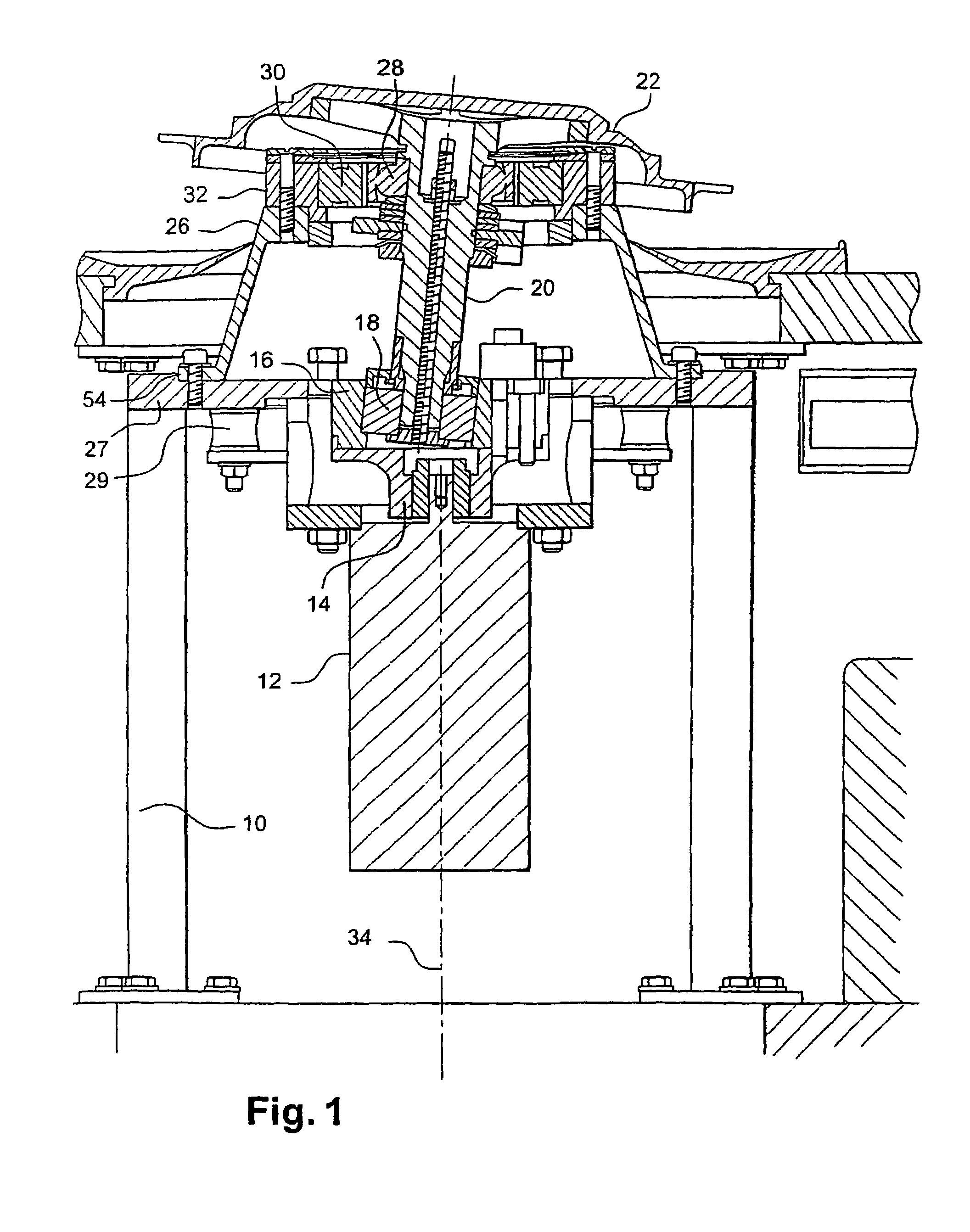
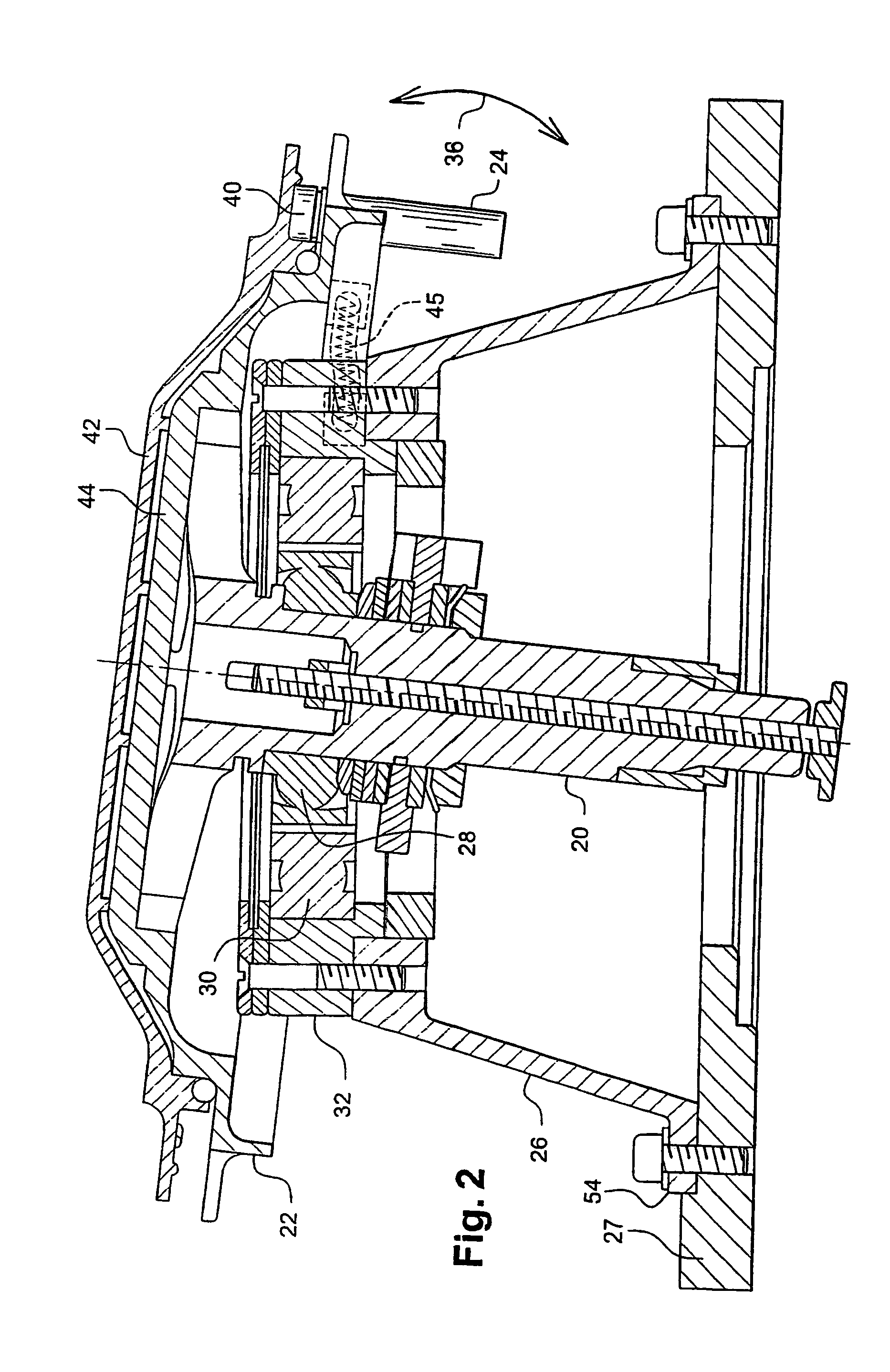
[0035]The embodiment shown in FIGS. 1 and 2 of the apparatus of the invention comprises a frame 10 with a bottom portion containing an electric motor 12 whose outlet shaft 14 extends vertically upwards and carries a turntable 16 having a rolling bearing 18 mounted obliquely and off-center. The bearing 18 receives the bottom end of a sloping shaft 20 formed by an endpiece that is axially cylindrical and projects from a disk 22 for supporting sample tubes 24, the disk 22 extending perpendicularly to the shaft 20 and being secured to the end thereof or being formed integrally with the shaft 20, as shown. The bearing 18 is inclined so as to be axially in alignment with the shaft 20, and it is preferably of the spherical type in order to accommodate small mechanical defects.

[0036]The disk 22 is supported and centered on a ring 26 carried by the frame 10, by means of two concentric bearings 28, 30 mounted one inside the other between the shaft 20 and the ring 26 and shown diagrammatically...


PUM

PropertyMeasurementUnit
angleaaaaaaaaaa
angleaaaaaaaaaa
speedaaaaaaaaaa

Abstract

Apparatus for rapidly vibrating tubes containing samples, e.g. biological samples, comprises a tube-support disk and concentric bearings for mounting the disk in a ring that is resiliently-suspended from a frame, the bearings comprising two rolling bearings mounted one within the other. The invention enables the tubes containing samples to be subjected to curvilinear reciprocating motion at high frequency.

Description

CROSS-REFERENCE TO RELATED APPLICATIONS[0001]This application is a continuation of PCT / FR03 / 02253, filed Jul. 16, 2003, claiming priority from French Application Nos. 02 09832, filed Aug. 1, 2002 and 03 02308, filed Feb. 25, 2003 which are hereby incorporated herein in its entirety by reference.BACKGROUND OF THE INVENTION[0002]The invention relates to apparatus for rapidly vibrating tubes containing samples, in particular biological samples, the rapid vibration of the tubes serving to grind up the samples.[0003]It is already known to grind up biological samples by enclosing the samples in tubes that also contain microbeads made of glass or ceramic, and by subjecting the tubes that are closed in leaktight manner to axial vibration at high speed, e.g. at about 100 hertz (Hz), for a relatively short duration, of the order of 30 seconds (s) to 60 s, for example.[0004]U.S. Pat. No. 5,567,050 describes apparatus for performing such a method and comprising a tube support disk and means for...

Claims


Application Information

Patent Timeline
Patent Type & Authority Patents(United States)
IPC IPC(8): B01F11/00G01N1/28B01F11/02B01L3/14C12M1/33C12M3/08C12N15/10F16H23/04
CPCB01F11/0028B01F31/26C12N15/10B01F31/00B01F31/80
Inventor ESTEVE, ALAINBOQUET, JEAN
Owner BERTIN TECHNOLOGIES
Learn More