
Storage system, and control method, job scheduling processing method, and failure handling method therefor, and program for each method

a storage system and cache memory technology, applied in the field of storage systems, can solve the problems of reducing the total input/output processing performance of storage, and losing data which has not been saved to the disk, so as to prevent the loss of important data, high priority, and quick detachment of dirty data in cache memories

Inactive Publication Date: 2006-08-29
HITACHI LTD
View PDF23 Cites 31 Cited by
  • Summary
  • Abstract
  • Description
  • Claims
  • Application Information

AI Technical Summary

Benefits of technology

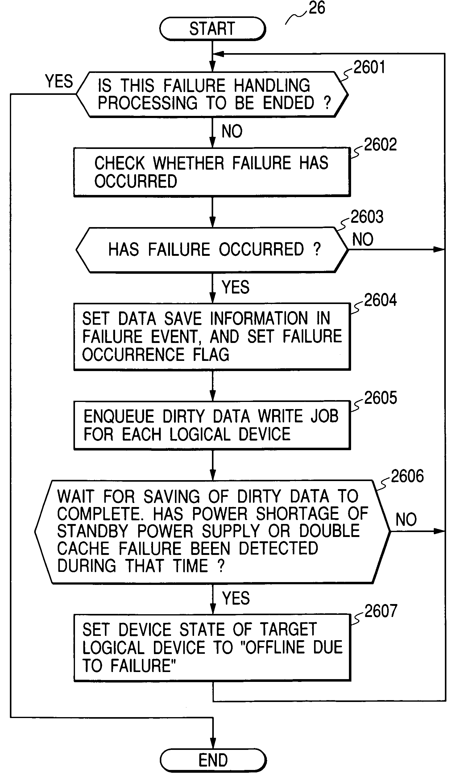
The present invention is a storage system that can quickly save data from cache memories to disk devices in the event of a failure, preventing loss of important data with a high priority. The storage system performs the steps of mapping more physical devices to a logical device with a high priority based on the first priority information and controlling data held in the cache memory and belonging to a logical device to be saved to a plurality physical devices mapped to the logical device. This can prevent performance reduction of important tasks with a high priority whenever possible in the event of a failure in the storage system.

Problems solved by technology

Even with the above prior art technique 1, the dirty data in the cache memories might be lost in the event of a failure, as described later.
However, when it has become unable to use the standby power supply due to continued power failure or when a double failure has occurred in the cache memories or shared memories, prior art technique 1 loses data which has not been saved to the disks, whether the data is important or not.
Further, to ensure data integrity, prior art technique 1 performs synchronous write operation in the event of a failure, which reduces the total input / output processing performance of the storage.

Method used


Image

  • Storage system, and control method, job scheduling processing method, and failure handling method therefor, and program for each method
  • Storage system, and control method, job scheduling processing method, and failure handling method therefor, and program for each method
  • Storage system, and control method, job scheduling processing method, and failure handling method therefor, and program for each method

Examples


Embodiment Construction

[0042]A preferred embodiment of the present invention will be described below with reference to the accompanying drawings.

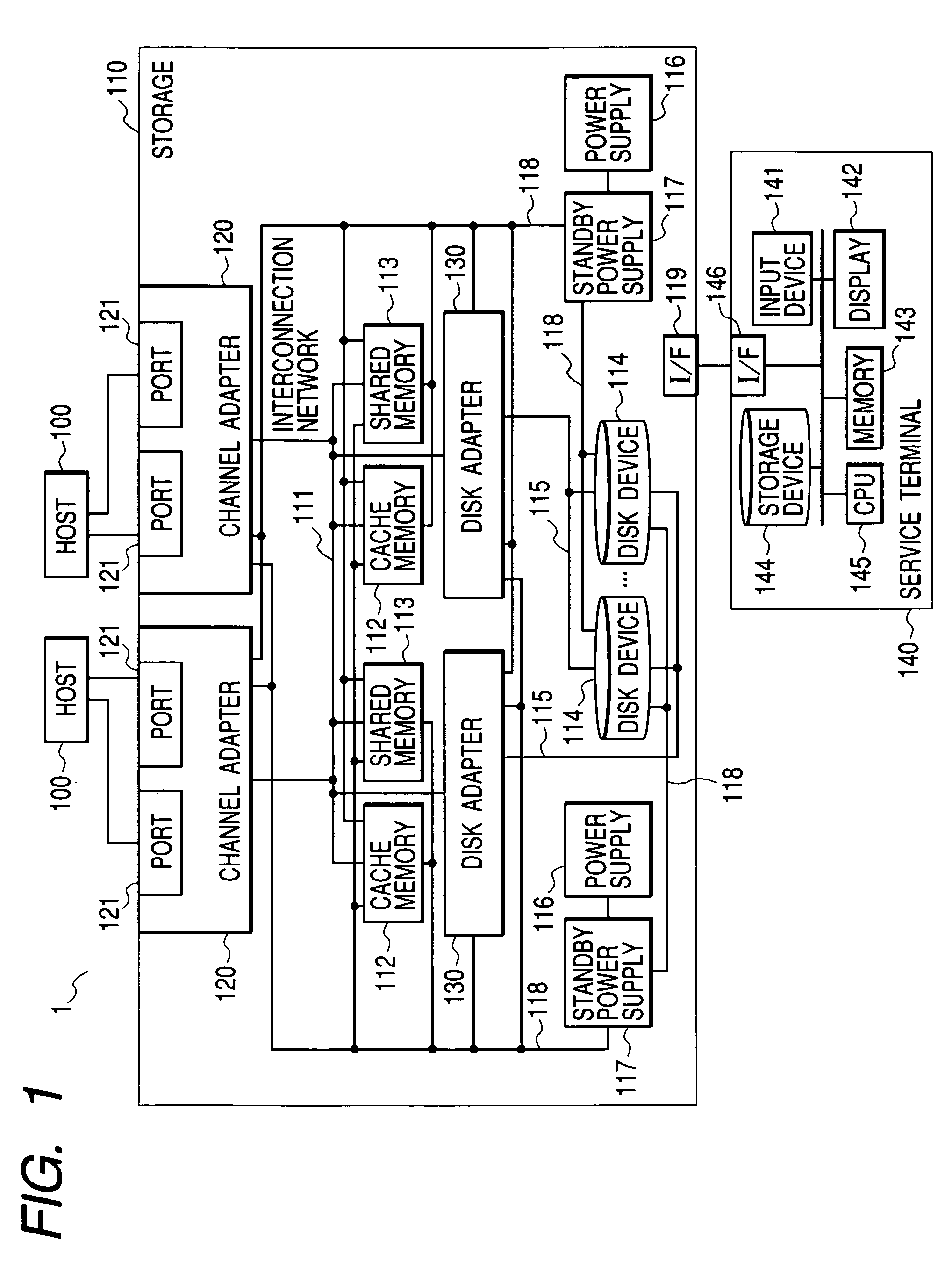
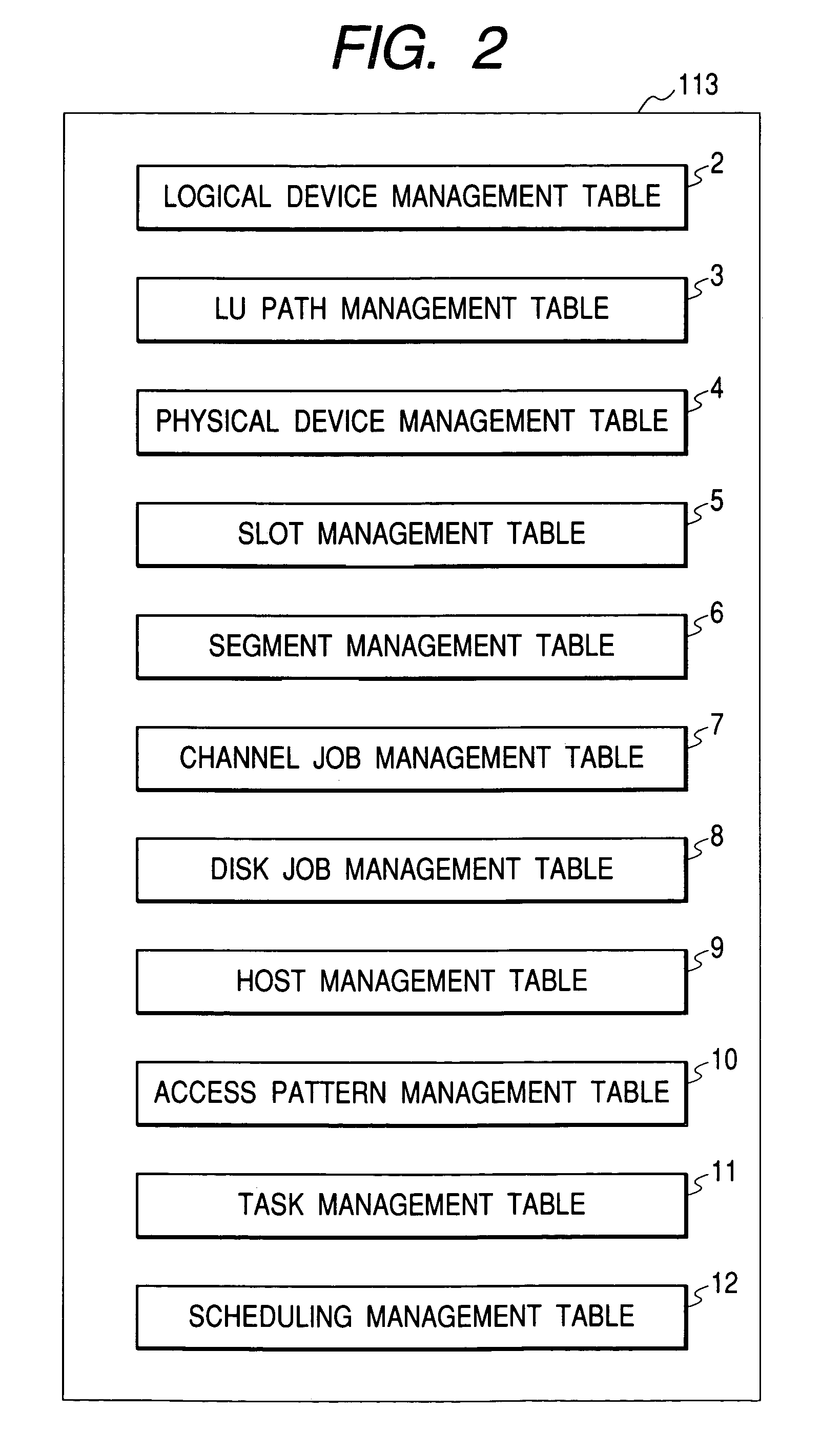
[0043]The present embodiment of the invention aims to, when a failure has occurred in storage 110, quickly destage to disk devices 114 dirty data in cache memories 112 which has not yet been reflected in the disk devices 114. The present embodiment accomplishes this by optimizing, beforehand, the physical devices to which the logical devices are mapped. When a failure has occurred in the storage 110, the storage 110 destage the dirty data (belonging to the logical devices) to the disk devices 114 in priory order set for the logical devices through a service terminal 140 beforehand. The service terminal 140 is used and managed by the storage manager through an input device. In such a case (when a failure has occurred in the storage 110), the storage 110 also schedules jobs to be executed therein based on priority order set through the service terminal 140, beforeh...


PUM


Abstract

An arbitrary number of a plurality of physical devices are mapped to each logical device provided for a host as a working unit, while considering a priority given to each logical device, and with each physical device being made up of a plurality of disk devices. This arrangement allows dirty data to be quickly saved to the disk devices in the order of logical device priority in the event of a failure. Furthermore, jobs are preferentially processed for important tasks in the event of a failure to reduce deterioration of the host processing performance.

Description

BACKGROUND OF THE INVENTION[0001]The present invention relates to a storage system.[0002]One known prior art technique (hereinafter referred to as prior art technique 1) described in Japanese Patent Laid-Open No. 11-167521 (1999) employs a common bus system so that logical modules, such as host adapters and storage adapters, as well as cache memories and disk devices can be added to the system according to the system configuration (scale), creating a scalable storage system. In this storage system, each logical module, disk device, and common bus are multiplexed, enabling an operation in a degraded mode, “hot-plugging” of the logical modules and storage media, and hence maintenance of the system without a system shutdown.[0003]Many of the disk control devices disposed between hosts and disk devices for controlling data transfer therebetween, such as those employed by the above prior art technique 1, each include a cache memory for temporarily storing data to be transferred. However,...

Claims


Application Information

Patent Timeline
Patent Type & Authority Patents(United States)
IPC IPC(8): G06F11/00G06F12/08G06F3/06
CPCG06F11/1441G06F12/0804G06F12/0873G06F3/061G06F3/0617G06F3/0631G06F2212/261G06F3/0689
Inventor WATANABE, YASUOYAMAMOTO, YASUTOMOEGUCHI, YOSHIAKI
Owner HITACHI LTD
Learn More