
Reduced chop rate analog to digital converter system and method

a digital converter and chop rate technology, applied in transmission systems, physical parameters compensation/prevention, instruments, etc., can solve the problems of fixed level of undesirable input current and input impedance reduction, and achieve the effect of reducing the chop rate analog to digital converter

Active Publication Date: 2006-08-29
ANALOG DEVICES INC
View PDF10 Cites 58 Cited by
  • Summary
  • Abstract
  • Description
  • Claims
  • Application Information

AI Technical Summary

Benefits of technology

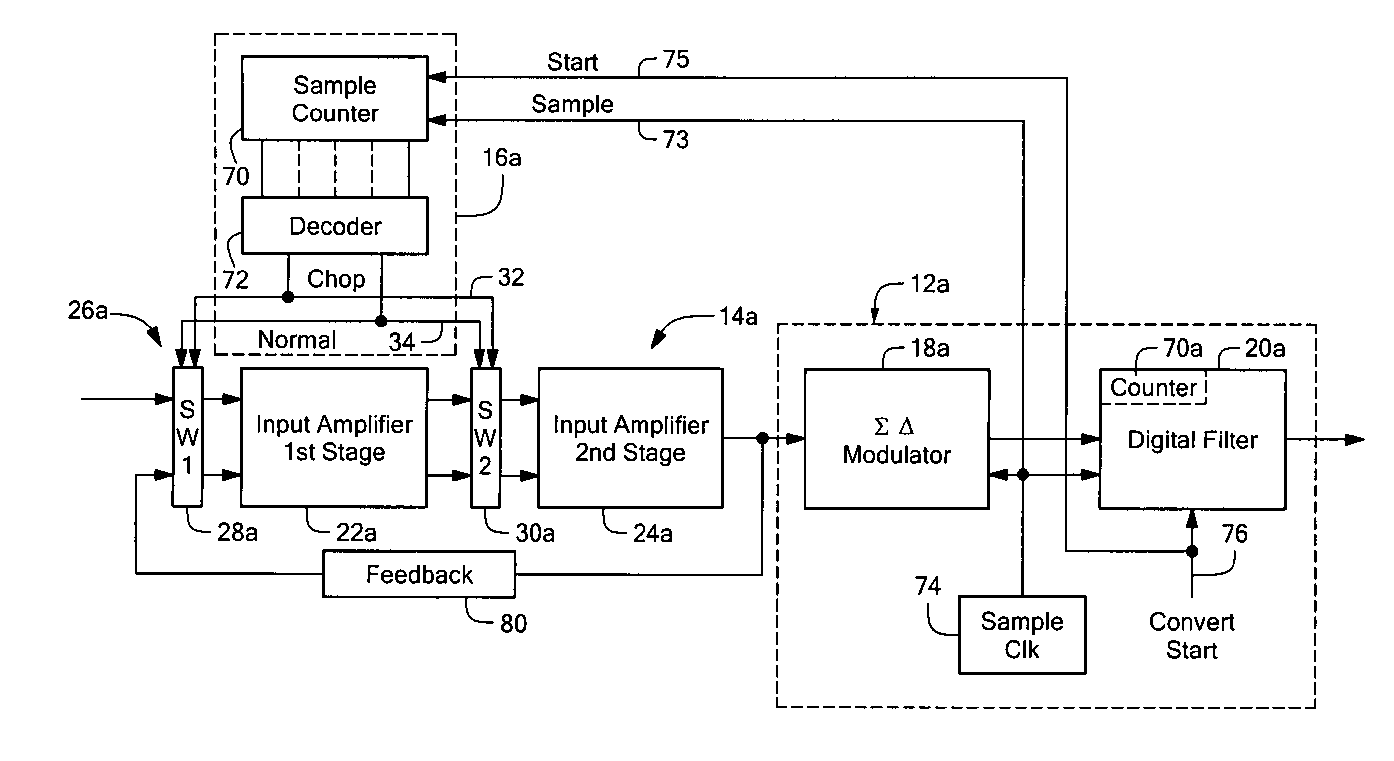
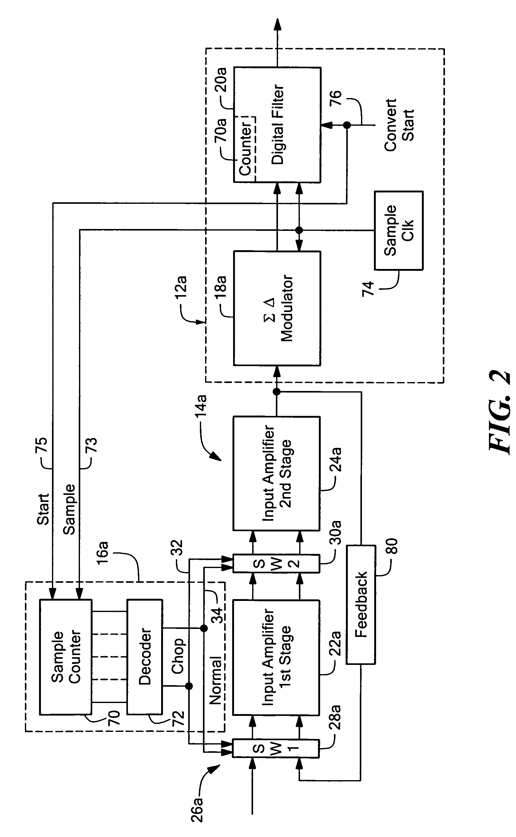
The invention is a system and method for analog to digital conversion that improves the reduction of errors and input current. It uses a chopping technique with filters that have symmetrical and non-symmetrical time responses. The system includes an analog to digital converter with a sampling quantizer circuit and a digital filter that selectively weights its input samples in accordance with its time response. The system also includes an input amplifier with a chopper circuit for alternately inverting the polarity of an input error. The invention achieves these improvements by selectively weighting input samples in accordance with the time response of the digital filter and generating the positive and negative error components in a plurality of time response intervals of the digital filter. The system can cancel out input errors and reduce the amount of undesirable input current.

Problems solved by technology

One problem with chopping is that it introduces an input current which causes a reduction in input impedance.
The chopping rate then causes a fixed level of undesirable input current independent of output rate.

Method used


Image

  • Reduced chop rate analog to digital converter system and method
  • Reduced chop rate analog to digital converter system and method
  • Reduced chop rate analog to digital converter system and method

Examples


Embodiment Construction

[0030]Aside from the preferred embodiment or embodiments disclosed below, this invention is capable of other embodiments and of being practiced or being carried out in various ways. Thus, it is to be understood that the invention is not limited in its application to the details of construction and the arrangements of components set forth in the following description or illustrated in the drawings. If only one embodiment is described herein, the claims hereof are not to be limited to that embodiment. Moreover, the claims hereof are not to be read restrictively unless there is clear and convincing evidence manifesting a certain exclusion, restriction, or disclaimer.

[0031]There is shown in FIG. 1 one embodiment of a reduced chop rate analog to digital converter 10 according to this invention including analog to digital converter 12, input amplifier 14, and a balanced filter response chopper timer 16. Analog to digital converter 12 may include a sampling quantizer circuit 18 and digital...


PUM


Abstract

A reduced chop rate analog to digital converter technique including selectively weighting input samples to a digital filter, alternately inverting the polarity of an input error into positive and negative error components; and generating the positive and negative error components in a plurality of time response intervals of the digital filter in which the sum of the weights of the positive and negative error components are substantially equal.

Description

RELATED APPLICATIONS[0001]This application claims the benefit of U.S. Provisional Application No. 60 / 536,581 filed Jan. 15, 2004, entitled: “Reduced Rate Chopping in an A / D Conversion System”, incorporated by reference herein.FIELD OF THE INVENTION[0002]This invention relates to a reduced chop rate analog to digital converter system and method, and more particularly to such a method and system in which the digital filter places equal weighting on positive and negative input error components.BACKGROUND OF THE INVENTION[0003]Chopping is frequently used to eliminate amplifier offset. For example, switches at the input and output of a differential amplifier are operated to reverse the polarity of the offset error so that it appears at the output alternately as positive and negative offsets which are then filtered out to eliminate the offset from the primary signal. Chopping also addresses the 1 / f flicker noise problem, which is becoming more of a problem in process geometries in the 0.2...

Claims


Application Information

Patent Timeline
Patent Type & Authority Patents(United States)
IPC IPC(8): H03M1/06H03M3/00
CPCH03M3/34H03M3/458
Inventor O'DOWD, JOHNMEANY, THOMAS J.TANSLEY, TOMAS
Owner ANALOG DEVICES INC
Learn More