
Traction chair system

a traction device and a technology of a traction chair, applied in the direction of pedestrian/occupant safety arrangements, vehicular safety arrangements, safety belts, etc., can solve the problems of not being able to efficiently relieve the pressure applied to conventional traction devices do not directly relieve the pressure on the lower back of an individual, so as to achieve efficient relief for an individual's lower back pain

Active Publication Date: 2006-08-29
BAUNE ROBERT D
View PDF19 Cites 38 Cited by
  • Summary
  • Abstract
  • Description
  • Claims
  • Application Information

AI Technical Summary

Benefits of technology

[0007]In view of the foregoing disadvantages inherent in the known types of traction devices now present in the prior art, the present invention provides a new traction chair system construction wherein the same can be utilized for efficiently relieving an individual of lower back pain.
[0013]A second object is to provide a traction chair system for efficiently relieving an individual of lower back pain.
[0016]A further object is to provide a traction chair system that is simple to operate.

Problems solved by technology

While these devices may be suitable for the particular purpose to which they address, they are not as suitable for efficiently relieving an individual of lower back pain.
Conventional traction devices do not directly relieve the pressure applied to the lower back of an individual because they focus upon relieving the pressure from the neck and upper back.

Method used


Image

  • Traction chair system
  • Traction chair system
  • Traction chair system

Examples


Embodiment Construction

A. Overview

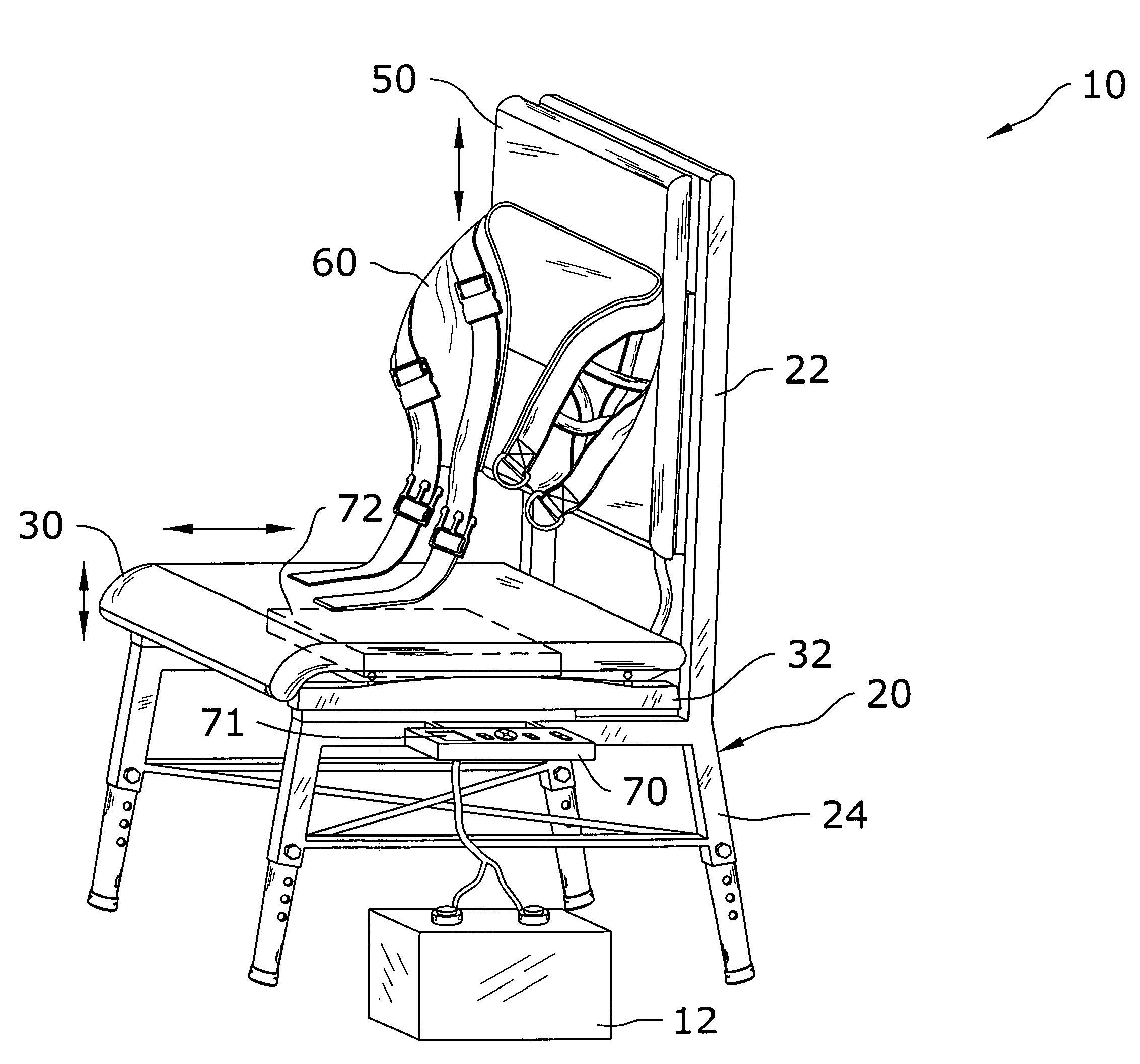
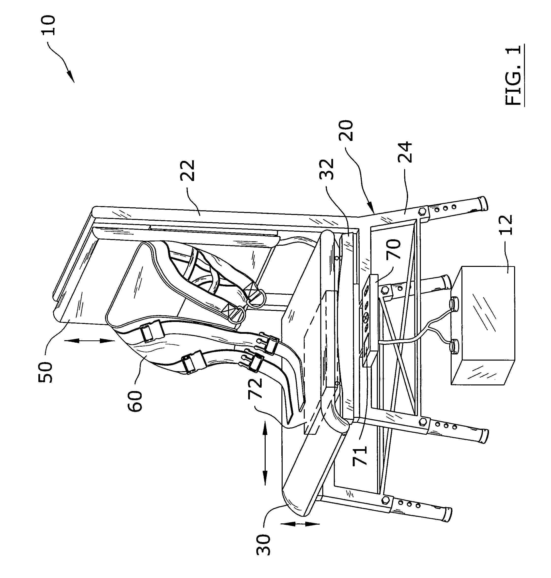
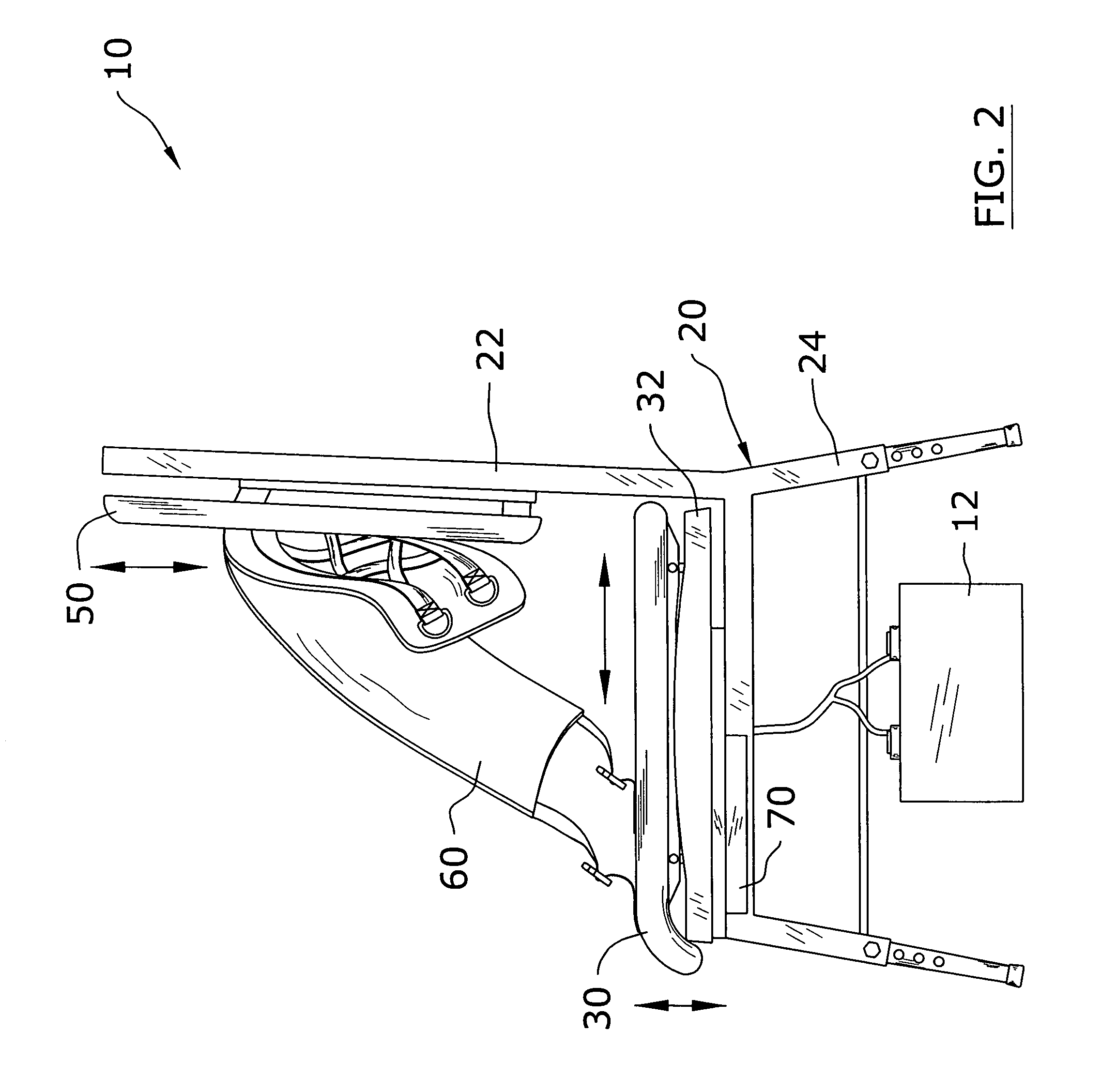
[0032]Turning now descriptively to the drawings, in which similar reference characters denote similar elements throughout the several views, FIGS. 1 through 9 illustrate a traction chair system 10, which comprises a chair frame 20, a seat 30, a plurality of actuators 40 attached between the chair frame 20 and the seat 30 for elevating / lowering the seat 30, a backrest 50, a harness 60 attached to the backrest 50 for securing an individual to the backrest 50, a motor 44 mechanically elevating / lowering the backrest 50, and a control unit 70 in communication with the actuators 40 and the motor 44. A scale 72 is positioned within the seat 30 and in communication with the control unit 70 for providing feedback to the individual regarding the actual amount of traction occurring. The amount of traction being applied to an individual is shown upon a display 71 of the control unit 70.

B. Chair Frame

[0033]The chair frame 20 preferably has an upper frame 22 extending from a lower fram...


PUM


Abstract

A traction chair system for efficiently relieving an individual of lower back pain. The traction chair system includes a chair frame, a seat, a plurality of actuators attached between the chair frame and the seat for elevating / lowering the seat, a backrest, a harness attached to the backrest for securing an individual to the backrest, a motor mechanically elevating / lowering the backrest, and a control unit in communication with the actuators and the motor. A scale is positioned within the seat and in communication with the control unit for providing feedback to the individual regarding the actual amount of traction occurring. The amount of traction being applied to an individual is shown upon a display of the control unit.

Description

BACKGROUND OF THE INVENTION[0001]1. Field of the Invention[0002]The present invention relates generally to traction devices and more specifically it relates to a traction chair system for efficiently relieving an individual of lower back pain.[0003]2. Description of the Related Art[0004]Traction devices have been in use for years. A commonly utilized traction device is a harness structure that attaches about an individual's head and applies an upward force to the head thereby causing the pressure to be partially relieved from the individual's back.[0005]While these devices may be suitable for the particular purpose to which they address, they are not as suitable for efficiently relieving an individual of lower back pain. Conventional traction devices do not directly relieve the pressure applied to the lower back of an individual because they focus upon relieving the pressure from the neck and upper back.[0006]In these respects, the traction chair system according to the present inve...

Claims


Application Information

Patent Timeline
Patent Type & Authority Patents(United States)
IPC IPC(8): A61F5/00
CPCA61F5/3769A61H1/0218A61H1/0229A61H2203/0431A61H1/0292A61H2201/1621
Inventor BAUNE, ROBERT D.
Owner BAUNE ROBERT D
Learn More