
Phase step alert signal for GPS integrity monitoring

a gps integrity and alert signal technology, applied in the direction of instruments, measurement devices, electrical appliances, etc., can solve the problems of gps receivers not being able to accurately determine position and/or time, gps signal errors can be caused, and malfunctions can introduce errors into the transmission of gps signals, etc., to achieve confidence in the integrity of gps signals

Inactive Publication Date: 2006-08-22
LOCKHEED MARTIN CORP
View PDF5 Cites 32 Cited by
  • Summary
  • Abstract
  • Description
  • Claims
  • Application Information

AI Technical Summary

Benefits of technology

[0019]In this manner, the present invention provides the ability of a GPS satellite to verify the accuracy and / or integrity of its own GPS signal, and then alert a user of the GPS signal error simply by shifting the phase of the GPS signal from an initial value by a predetermined phase-shift amount. The GPS user / receiver can then detect the phase shift timing which indicates an error with the GPS signal, and decide whether or not to use, that particular GPS signal. Confidence in the integrity of the GPS signal is thereby simply provided to the user without the need for a separate communication channel, and without the need for a costly and complex ground integrity system.
[0022]In this manner, the present invention provides the ability of a GPS satellite to verify the accuracy and / or integrity of its own GPS signal, and then alert a user of the GPS signal error simply by shifting the phase of the GPS signal from an initial value by a predetermined phase-shift amount according to a timing pattern. The GPS user / receiver can then detect the phase shift which indicates an error with the GPS signal, and decide whether or not to use that particular GPS signal. Confidence in the integrity of the GPS signal is thereby simply provided to the user without the need for a separate communication channel, and without the need for a costly and complex ground integrity system.

Problems solved by technology

Although the Global Positioning System (GPS) provides very accurate position and time information, there are times when GPS satellite system malfunctions can introduce errors into the GPS signal transmitted from the GPS satellite.
When this occurs, the GPS receivers will not be able to accurately determine position and / or time.
GPS signal errors can be caused by a number of conditions.
For example, if one of the GPS satellite transmitter elements, or any of the other satellite components, fail, the GPS signal waveform can become corrupted.
For example, an output amplifier in the GPS satellite may start to malfunction and thereby corrupt the transmitted signal.
Another source of error is a failure of the satellite's atomic clock.
If a clock failure occurs, the satellite will transmit incorrect time data and introduce error into the computed position information.
Another potential error is the transmission of erroneous correction data from GPS ground stations to GPS satellites.
If a ground station sends the wrong correction data, then the GPS satellites will produce inaccurate or erroneous output signals.
Errors in GPS signals can lead to severe safety issues or inefficient operation for many systems that use GPS signals, such as aircraft systems, transportation systems, weapon systems and so forth.
It can be appreciated that errors in the received GPS signal in an aircraft navigation system could lead to mid-air crashes or other dangerous situations.
Thus, for example, it is possible that a current GPS satellite could produce a probability of error ten thousand times higher than the FAA's desired goal.
Thus, it will be a very important safety issue for these systems to ensure the integrity of the received GPS signals.
The WAAS integrity monitoring system will require an enormous cost including the cost of building the new WAAS ground stations, procuring the new geostationary messaging satellites, and the costs of maintaining and operating the ground stations.
Moreover, the WAAS may not be able to signal a problem with GPS integrity with sufficient speed.

Method used


Image

  • Phase step alert signal for GPS integrity monitoring
  • Phase step alert signal for GPS integrity monitoring
  • Phase step alert signal for GPS integrity monitoring

Examples


Embodiment Construction

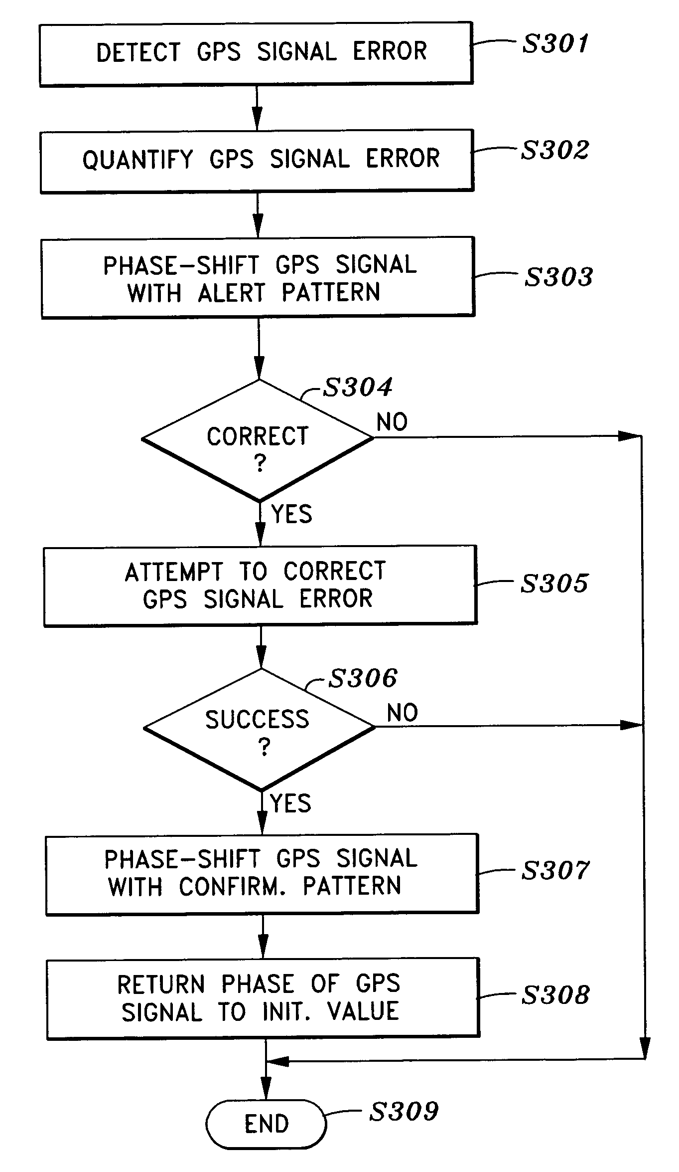
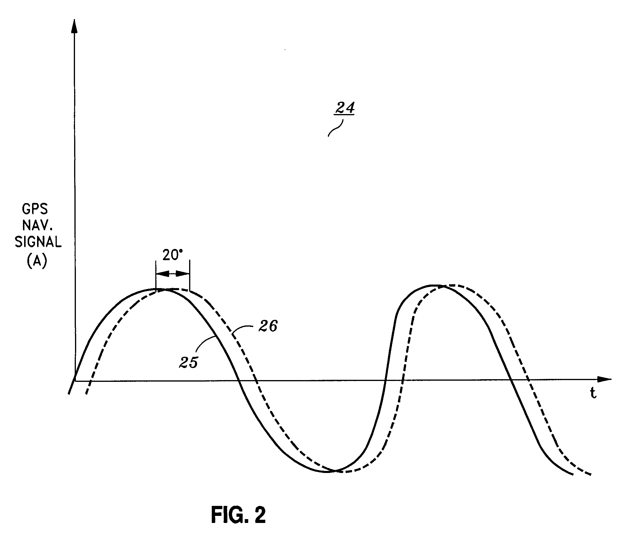
[0030]As mentioned above, the present invention is generally directed to system and method for providing the ability of a GPS satellite to verify the accuracy and / or integrity of its own GPS signal, and alerting a user of the GPS signal error by shifting the phase of the GPS signal from an initial value by a predetermined phase-shift amount according to a timing pattern. The GPS user / receiver can detect the phase shift which indicates an error, and decide whether or not to use, or continue using, that particular GPS signal.

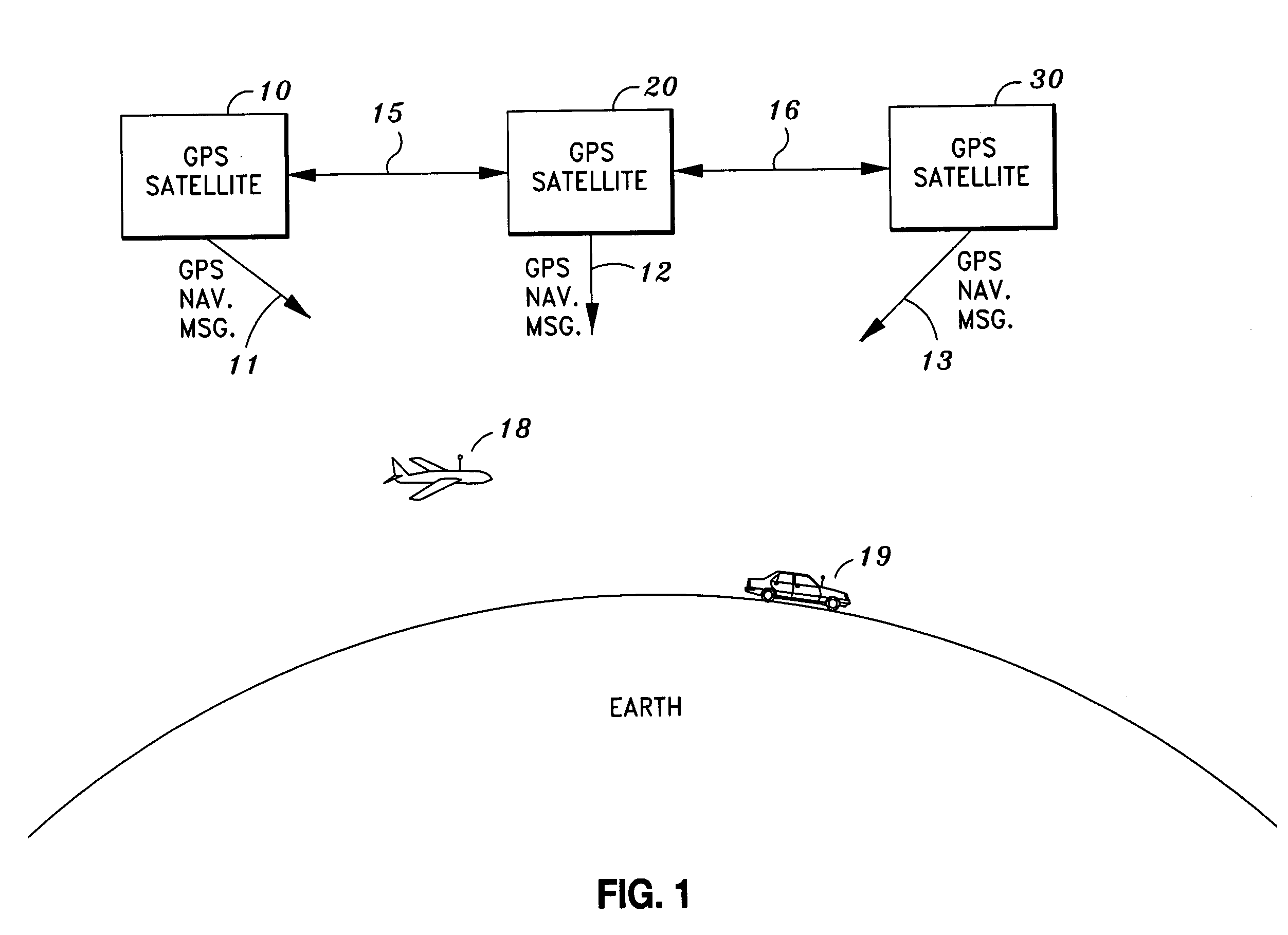
[0031]Turning to the drawings, FIG. 1 shows a global positioning system (GPS) environment in which the present invention can be practiced. As seen in FIG. 1, the global positioning system (GPS) includes in-view GPS satellites 10, 20 and 30 which transmit GPS navigation signals 11, 12 and 13, respectively. A receiver can be used to receive GPS navigation signals 11, 12 and 13 and then determine the position of the receiver based on the position data in each of GPS ...


PUM


Abstract

Alerting a user of an integrity error in a global positioning system (GPS) signal transmitted from a transmitter in a global positioning system (GPS) satellite, by detecting an error in the global positioning system (GPS) signal, alerting the user of the error by shifting a phase of the global positioning system (GPS) signal from an initial value by a predetermined phase-shift amount, and returning, in the case that the detected error is corrected, the phase of the global positioning system (GPS) signal to the initial value. Preferably, the GPS signal is phase-shifted by the predetermined phase-shift amount using an alert timing pattern which indicates the level of detected error.

Description

STATEMENT AS TO RIGHTS TO INVENTIONS MADE UNDER FEDERALLY SPONSORED RESEARCH OR DEVELOPMENT[0001]NOT APPLICABLE TO THIS INVENTION.BACKGROUND OF THE INVENTION[0002]1. Field of the Invention[0003]The present invention concerns providing an integrity alert to a user of the Global Positioning System (GPS) when the signal contains an error. Specifically, the invention concerns alerting the user of the signal error by shifting the phase of the Global Positioning System (GPS) signal from an initial value by a predetermined phase-shift amount.[0004]2. Description of the Related Art[0005]The use of the Global Positioning System (GPS) is increasing rapidly in a variety of applications. Accordingly, the users of GPS expect to have, and often must have, confidence in the integrity and accuracy of the GPS signal. U.S. Pat. No. 6,603,426, (hereinafter “the '426 patent”), issued Aug. 5, 2003, sets forth one solution to this problem by the same applicant of the present invention.[0006]As explained ...

Claims


Application Information

Patent Timeline
IPC IPC(8): G01S5/02H04B7/185G01S5/14G01S19/23G01S19/29
CPCG01S19/02G01S19/20
Inventor CLARK, RONALD H.
Owner LOCKHEED MARTIN CORP
Learn More