
Fixed material transportation apparatus, fixed material discharging apparatus, method for discharging the fixed material, and liquid fixing apparatus

a technology for fixing materials and transportation apparatuses, which is applied in the direction of printing, other printing apparatus, etc., can solve the problems of not realizing construction transporting and discharging by sandwiching with such two pairs of rollers, generating uneven recording of ink particles by dispersion of flying distance, and preventing more useful cockling of fixed materials

Inactive Publication Date: 2006-08-22
SEIKO EPSON CORP
View PDF19 Cites 13 Cited by
  • Summary
  • Abstract
  • Description
  • Claims
  • Application Information

AI Technical Summary

Benefits of technology

This solution prevents cockling and spur marks, allowing for faster and more efficient printing without margin issues, improving overall printing quality and reducing printing time by enabling the use of all nozzles at normal speeds.

Problems solved by technology

There are faults that recording unevenness generates by dispersion of flying distance of ink particles because gap between the recording medium P and the recording head 9 becomes narrow and the recording medium P gets dirty because of attaching to the recording head 9 at generating the generation of the cockling.
Therefore, the cockling goes over allowance, and it is considerable that the construction transporting and discharging by sandwiching with such the two pairs of rollers itself is not realized depending on kinds of apparatus such as the ink jet printer having long head length and the like.
However, when the paper gap is large like this, ink particles discharged from the nozzle of the recording head generate flying curve and divergence of point of impact becomes large for the flying curve so as to prevent possibly from improving printing quality even at using needless exclusive sheet.
The spur mark is conspicuous especially at the normal sheet large in cockling and causes decreasing printing quality.
However, only through holes are opened to suck at the sucking portion of the hollow box shape in both of them, and it is difficult to prevent the above cockling over whole surface of the recording medium in the recording portion.
As the result, it can not prevent that the spur mark remains at the recording medium P.
Further, since the prior art described in the above official gazette has the construction that only through holes are opened to suck at the sucking portion of the hollow box shape, strong sucking force possibly causes fall of transporting accuracy.
That is, although ink run off from the upper and lower ends of the recording medium P is stuck on the transportation stage 5 at performing the printing without margin of upper and lower ends, the recording medium P is possibly contaminated when ink is stuck on the transportation stage 5.
Therefore, printing work time becomes long because printing speed without margin of upper and lower ends becomes slower than normal printing speed.

Method used


Image

  • Fixed material transportation apparatus, fixed material discharging apparatus, method for discharging the fixed material, and liquid fixing apparatus
  • Fixed material transportation apparatus, fixed material discharging apparatus, method for discharging the fixed material, and liquid fixing apparatus
  • Fixed material transportation apparatus, fixed material discharging apparatus, method for discharging the fixed material, and liquid fixing apparatus

Examples


second embodiment

[0078]FIG. 5 shows the recording medium transportation apparatus according to the invention. In FIG. 5, since a recording medium transportation apparatus 30 has an almost similar construction as the recording medium transportation apparatus 20 shown in FIG. 2, the description will be omitted adding the same symbols for the same components.

[0079]The recording medium transportation apparatus 30 has a construction different from the recording medium transportation apparatus 20 shown in FIG. 2 at the following point. That is, in the recording medium transportation apparatus 30, an auxiliary transporting device 31 is constructed by that a sucking hole 108 provided at the upper surface of the sucking portion 101 of the sucking device 100 inclines slantingly to discharging direction to the upper side as shown in FIG. 5 instead of the auxiliary transporting device 31 by the inclined upper surface of the sucking portion 101 of the sucking device 100 in the recording medium transportation app...

third embodiment

[0085]FIG. 6 shows a recording medium transportation apparatus of a The recording medium transportation apparatus includes a feed roller 11 and a hopper 12 as an automatic sheet feeder, a delivery roller 13, a driven roller 14, a transportation stage 50, and a main body portion 60 as a transportation apparatus, and a carriage 18 and a recording head 19 as a recording device.

[0086]The recording medium transportation apparatus supplies the recording medium P by the automatic sheet feeder and prints letter and picture by discharging ink droplet on the recording medium P using recording device while transporting the sheet by a delivering device. Transportation direction of the recording medium P shown with arrow in the figure is placed to F direction and scanning direction of the recording head 19 is placed to S direction hereafter.

[0087]FIG. 7 is a perspective view showing detailed example of the above transportation stage 50 and the main body portion 60, and FIG. 8 is a plane view th...


PUM


Abstract

The present invention involves a sucking device having a fixed material transportation surface including plural sucking holes, a decompression chamber connecting to the plural sucking holes, and a sucking device sucking air in the decompression chamber. The fixed material is fed on the fixed material transportation surface of the sucking device by the delivering device, and is stuck on the fixed material transportation surface through the sucking holes by the sucking device. The fixed material is fixed by a fixing head at the state of being stuck and is transported gradually to a downstream side by the delivering device on the fixed material transportation surface. When fixing is finished, the fixed material separates from the surface of the fixed material transportation surface and rises slightly by blowing air from the sucking holes by a blowing device so as to move to a discharging direction.

Description

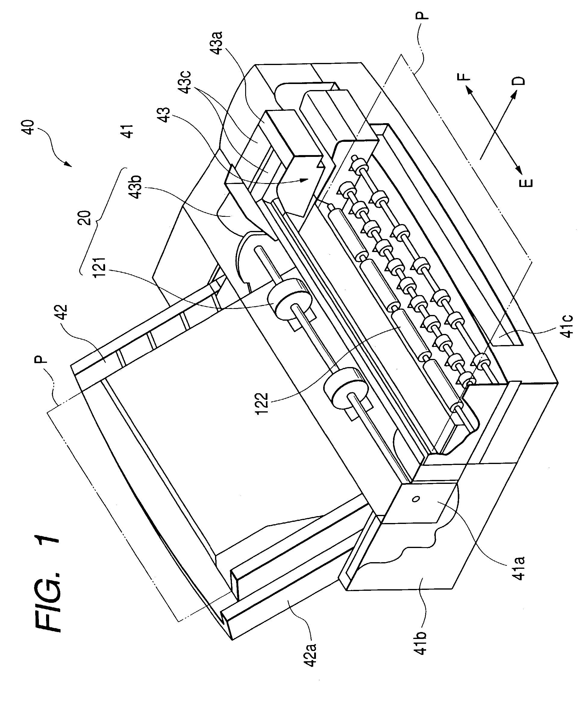
BACKGROUND OF THE INVENTION[0001]The present invention relates to a fixed material transportation apparatus, an fixed material discharging apparatus, a method for discharging the fixed material, and a liquid fixing apparatus having the carrier apparatus and the discharging the apparatus, particularly to technology for drawing, keeping, and discharging smoothly the fixed material in a recording portion of the liquid fixing apparatus after finishing to fix.[0002]FIG. 15 is a side view showing an example of inner construction of an ink jet printer being one of general liquid fixing apparatus and discharging recording a medium. The ink jet printer includes a sheet feed roller 1 and a hopper 2 as an automatic sheet feeder, includes a delivery roller 3, a driven roller 4, a transportation stage 5, a discharging roller 6, and a roller with teeth (a discharging serrated roller) 7 as a carrier, and includes a carriage 8 and a recording head 9 as a recorder.[0003]The ink jet printer having su...

Claims


Application Information

Patent Timeline
Patent Type & Authority Patents(United States)
IPC IPC(8): B41J2/01B41J11/00B41J11/06
CPCB41J11/005B41J11/06B41J11/0085B41J11/0065
Inventor ISHII, TAKAYUKISESHIMO, TATSUYA
Owner SEIKO EPSON CORP
Learn More