
Model-assisted reconstruction of volumetric data

a technology of volumetric data and model, applied in the direction of material analysis using wave/particle radiation, conversion screens, nuclear engineering, etc., can solve the problems of long measurement time to produce the needed measurements, unpractical to use these types of methods, and slow inspection techniques listed previously can not provide much useful information about these dynamic processes

Inactive Publication Date: 2006-08-15
IOWA STATE UNIV RES FOUND
View PDF33 Cites 39 Cited by
  • Summary
  • Abstract
  • Description
  • Claims
  • Application Information

AI Technical Summary

Benefits of technology

"The present invention provides a way to get three-dimensional information about an object and use it in manufacturing processes or other applications. It uses a structural model of an object and inspection data from the object to create a three-dimensional image. The invention also allows for x-ray inspection of a dynamic process and combines multiple inspection times to create a movie of the process. Overall, the invention helps to improve the inspection process and make it more efficient."

Problems solved by technology

The problem with these types of methods is that they often require long measurement times to produce the needed measurements.
Thus, it is not practical to use these types of methods.
The slow inspection techniques listed previously can not provide much useful information about these dynamic processes.
However, understanding the dynamics of this process is a challenging problem.
Although, real-time radiography of metal pours has given some insight into the problem, the images obtained are only two-dimensional projections that provide limited information on the dynamics of the process for complex geometries such as engine blocks.
Inspection issues include quantifying cracks, porosity, density gradients and delaminations between layers.
These same problems are encountered with a number of different types of objects, inspection techniques, and manufacturing processes.

Method used


Image

  • Model-assisted reconstruction of volumetric data
  • Model-assisted reconstruction of volumetric data
  • Model-assisted reconstruction of volumetric data

Examples


Embodiment Construction

[0020]The present invention relates to providing three-dimensional information about objects for visualization or other purposes. The present invention can be used with dynamic processes so is well-suited for various manufacturing processes. The present invention uses model information to assist in the reconstruction of three-dimensional information or a three-dimensional image of an object in combination with inspection data.

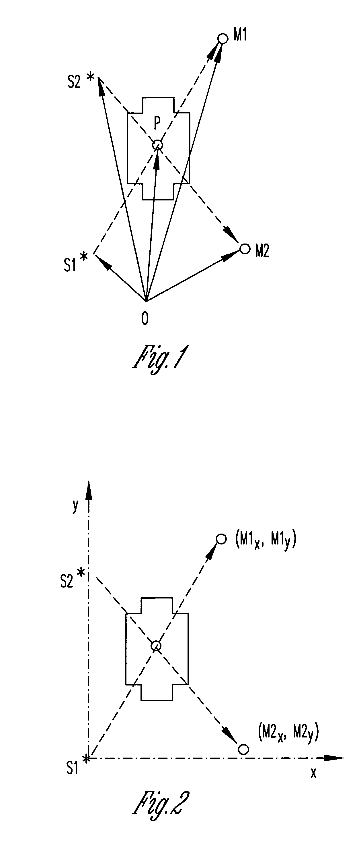
[0021]The present invention uses stereographic measurement methods. Stereographic measurement methods use two (or more) two-dimensional projections to calculate the three-dimensional location of the features in an object. Thus, two (or more) views can be used to produce a three-dimensional representation.

[0022]The general idea used in stereography measurements is indicated in FIG. 1. Two sources, S1 and S2 are used to produce projection images of a sample. A point of interest in the sample, P, will project to the points M1 and M2, which could be in a single det...


PUM

PropertyMeasurementUnit
material propertiesaaaaaaaaaa
porosityaaaaaaaaaa
timeaaaaaaaaaa

Abstract

The present invention is a method for inspecting objects. The method includes obtaining a structural model of a first object, the model providing dimensions and material properties for the first object, inspecting a second object to provide inspection data for at least two views of a structure of the second object, comparing inspection and predicted data based on the structural model of the first object and a simulation of the inspection process, reconstructing stereographic data for the second object based on the structural model of the first object and contributions of the inspection data of the second object. In another embodiment, where there is a structural model of an object, the object can be subjected to a dynamic process and the object is inspected throughout the process.

Description

CROSS-REFERENCE TO RELATED APPLICATIONS[0001]This application is a conversion of and claims benefit of priority from Provisional U.S. application 60 / 388,762 filed Jun. 14, 2002.BACKGROUND OF THE INVENTION[0002]In various manufacturing or other processes it is desirable to provide for nondestructive evaluation of items being produced. It is particularly desirable to provide for as complete as possible three dimensional information about an object, including both exterior and interior features. Various inspection techniques, such as computed tomography, magnetic resonance imaging, microwave, and acoustic wave imaging have been developed to address this need. The problem with these types of methods is that they often require long measurement times to produce the needed measurements. Thus, it is not practical to use these types of methods. Consider, for example, a case where the material being inspected is flowing, such as molten metal in a casting or fluid mixtures flowing through a pi...

Claims


Application Information

Patent Timeline
Patent Type & Authority Patents(United States)
IPC IPC(8): A61B6/02B22D46/00G06K9/62G06K9/64
CPCB22D46/00G06T7/0075G06T7/001G06T7/593
Inventor JENSEN, TERRENCE C.GRAY, JOSEPH N.
Owner IOWA STATE UNIV RES FOUND
Learn More