
Expectation-maximization-based channel estimation and signal detection for wireless communications systems

a wireless communication system and channel estimation technology, applied in the field of communication systems, can solve the problems of large error floor, inability to make reliable data decisions in ofdm systems, and loss of snr compared to coherent detection, so as to improve signal detection accuracy, efficient channel estimation, and improve signal detection

Inactive Publication Date: 2006-08-15
THE TRUSTEES FOR PRINCETON UNIV
View PDF7 Cites 65 Cited by
  • Summary
  • Abstract
  • Description
  • Claims
  • Application Information

AI Technical Summary

Benefits of technology

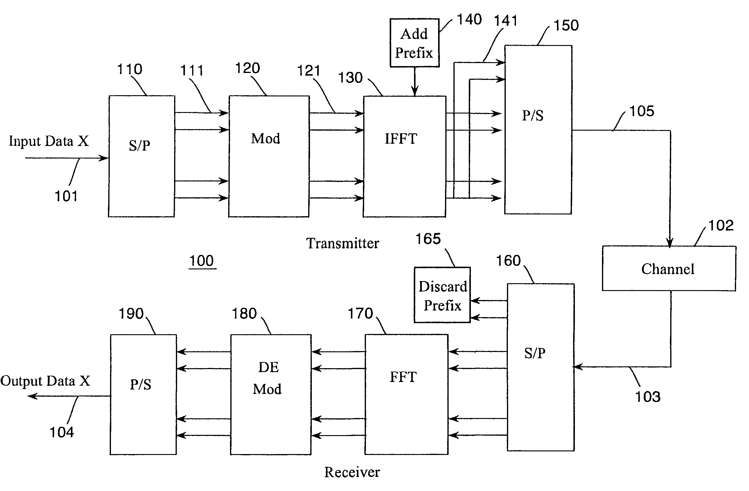
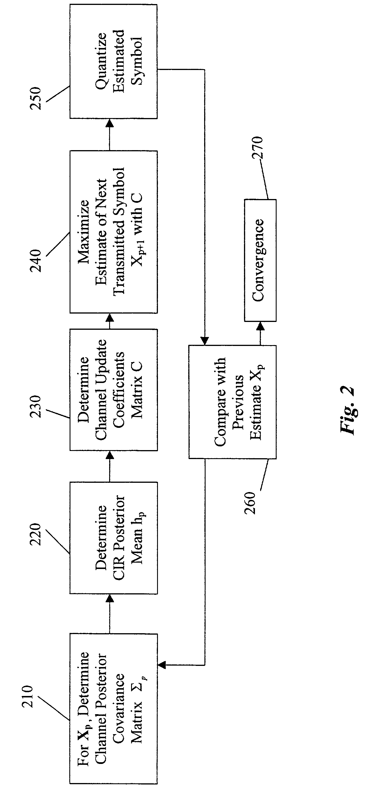
"The invention is a system and method for efficiently estimating channel states and detecting received symbols in a wireless communication system. It uses the expectation-maximization (EM) process to obtain a maximum likelihood estimate of the channel impulse response (CIR) and improve signal detection. The method iteratively updates the channel estimate and detects the received symbol until the estimates converge. The quantized estimate of the symbol is compared with the previous estimate to determine if the estimates have converged. The technical effect of the invention is to improve the accuracy of channel estimation and signal detection in wireless communication systems."

Problems solved by technology

However, it is not possible to make reliable data decisions in OFDM systems unless a good channel estimate is available.
Although differential detection could be used to detect the transmitted signals in the absence of channel information, this would result in about a 3 dB loss in SNR compared to coherent detection.
Shortcomings of those processes include a large error floor that may be incurred by a mismatch between the estimated and real CIRs, and difficulty in obtaining the correlation function of the channel impulse response.

Method used


Image

  • Expectation-maximization-based channel estimation and signal detection for wireless communications systems
  • Expectation-maximization-based channel estimation and signal detection for wireless communications systems
  • Expectation-maximization-based channel estimation and signal detection for wireless communications systems

Examples


Embodiment Construction

Expectation-Maximization

[0019]Our invention uses an expectation-maximization (EM) method to estimate statistical characteristics (parameters) of a wireless communications channel, and to detect signals in the estimated channel.

[0020]The EM method according to the invention includes two iterative steps: an expectation step and a maximization step. The expectation step is performed with respect to unknown underlying channel parameters, using a previous estimate of the parameters, conditioned upon incomplete observations. The maximization step then provides an improved estimate that maximizes the expectation of a log likelihood function defined over complete data, conditioned on the previous estimate and the next estimate. These two steps are iterated until the estimated values converge. See A. P. Dempster, N. M. Laird and D. B. Rubin, “Maximun likelihood estimation from incomplete data,”Journal of the Royal Statistical Society (B), Vol. 39, No. 1, 1977, pp. 1–38, and T. K. Moon, “The ...


PUM


Abstract

A system and method detect symbols of a modulated signal received via a plurality of channels of a wireless communications system. A symbol transmitted via the channels is initially estimated based on the channel estimate from either pilot symbol or previously estimated symbol, and then channel estimate is updated. The next estimate of the symbol is computed by using updated channel information and maximizing the expectation of the log likelihood function. The next estimate is then quantized according to the signal constellation. The quantized estimate of the symbol is compared with the previous estimate of the symbol to determine if the previous estimate of the symbol and the quantized next estimate of the symbol have converged. Otherwise, the quantized next estimate of the symbol is made as the input for the next iteration, and the updating, optimizing, quantizing, and comparing are repeated until the estimate converges.

Description

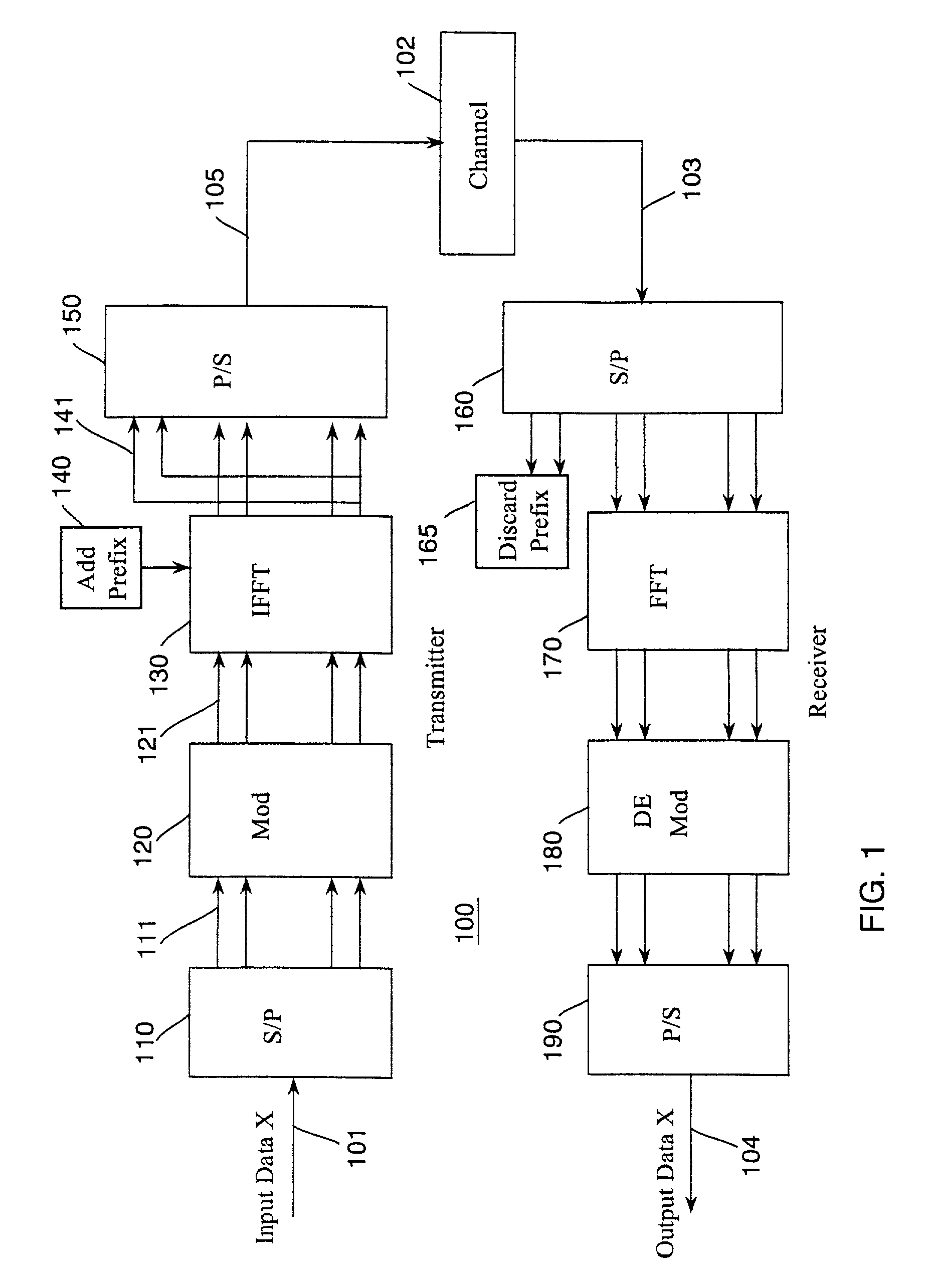
FIELD OF THE INVENTION[0001]The invention relates generally to communications systems, and more particularly to channel estimation and signal detection in wireless communications systems.BACKGROUND OF THE INVENTION[0002]Orthogonal frequency division multiplexing (OFDM) is a signal modulation technique in which a transmitter divides a signal, and then transmits the divided signal over several subcarriers. The subcarriers are located on a frequency axis at regular intervals. With the OFDM technique, in contrast with conventional serial communication techniques, the transmitted signal is divided into N streams, and the N stream are then transmitted in parallel over N subcarriers, each having a separate carrier frequency. The OFDM technique transmits the signal reliably and efficiently at a high data rate.[0003]The subcarriers are made “orthogonal” by appropriately selecting the spacing of the frequencies in the frequency band. Therefore, spectral overlapping among subcarriers is allowe...

Claims


Application Information

Patent Timeline
Patent Type & Authority Patents(United States)
IPC IPC(8): H03H7/30H03H7/40H04J11/00H04L25/02H04L27/26
CPCH04L25/0204H04L27/2647H04L25/0242H04L25/0224
Inventor MA, XIAOQIANGKOBAYASHISCHWARTZ, STUART C.GU, DAQINGZHANG, JINYUN
Owner THE TRUSTEES FOR PRINCETON UNIV
Learn More