Isolator/circuit-breaker device for electric substations

a technology of electric substations and isolation devices, which is applied in the direction of earthing switches, contact switches, air break switches, etc., can solve the problems of preventing the optimal use of available space, affecting the reliability of electric devices, and affecting the etc., to achieve the effect of reliable operation of circuit breakers and more reliable electric devices

Inactive Publication Date: 2006-08-15
AREVA T&D ITAL
View PDF20 Cites 16 Cited by
  • Summary
  • Abstract
  • Description
  • Claims
  • Application Information

AI Technical Summary

Benefits of technology

[0039]The mechanism for applying a rotational torque onto said circuit-breaker actuating shaft in at least one intermediate position along its length overcomes the problems of the deformation of the circuit-breaker actuating shaft and of the casing, thus resulting in a more reliable electric device.
[0040]According to a different aspect, the present technology provides an electric device comprising: a casing; at least one circuit-breaker having movable circuit-breaker contacts; at least one line isolator having a fixed isolator contact; at least one earthing isolator; a circuit-breaker actuating shaft for actuating at least one circuit-breaker; and a lever connected to a conductor rod co-operating with movable circuit-breaker contacts, wherein, each circuit-breaker is associated with a pair of said levers and wherein said levers are made of an electrically insulating material. This embodiment solves the problem of providing an electric device wherein the one or more circuit-breakers are electrically insulated from the circuit-breaker actuating shaft. The levers are robust and provide a reliable operation of the circuit-breakers.
[0041]According to a further aspect, the present technology provides an electric device having two or more phases, said device comprising: a casing; at least two circuit-breakers, at least two corresponding line isolators and at least two corresponding earthing isolators, wherein a segregation baffle is provided between a line isolator and a corresponding earthing isolator of a first phase and a line isolator and a corresponding earthing isolator of an adjacent second phase in order to segregate said first phase of the device from the adjacent second phase. This arrangement is advantageous as it intercepts any discharges between two adjacent phases.

Problems solved by technology

The line isolator shaft is situated at a distance from the circuit-breaker shaft and this complicates the arrangement of the various mechanisms inside the casing of the device and prevents optimum use of the available space, which is restricted by the small dimensions of the device.
Another problem associated with the operation of vacuum circuit-breakers consists in the extremely high pressing loads.
The Applicant has ascertained that such an essentially rigid configuration is unable to transfer (and maintain) in a sufficiently reliable and precise manner the abovementioned pressing loads onto the movable circuit-breaker contacts.
Furthermore, the Applicant has faced the problem to optimize the space inside the device and to provide an optimized arrangement within the device.

Method used


Image

  • Isolator/circuit-breaker device for electric substations
  • Isolator/circuit-breaker device for electric substations
  • Isolator/circuit-breaker device for electric substations

Examples


Embodiment Construction

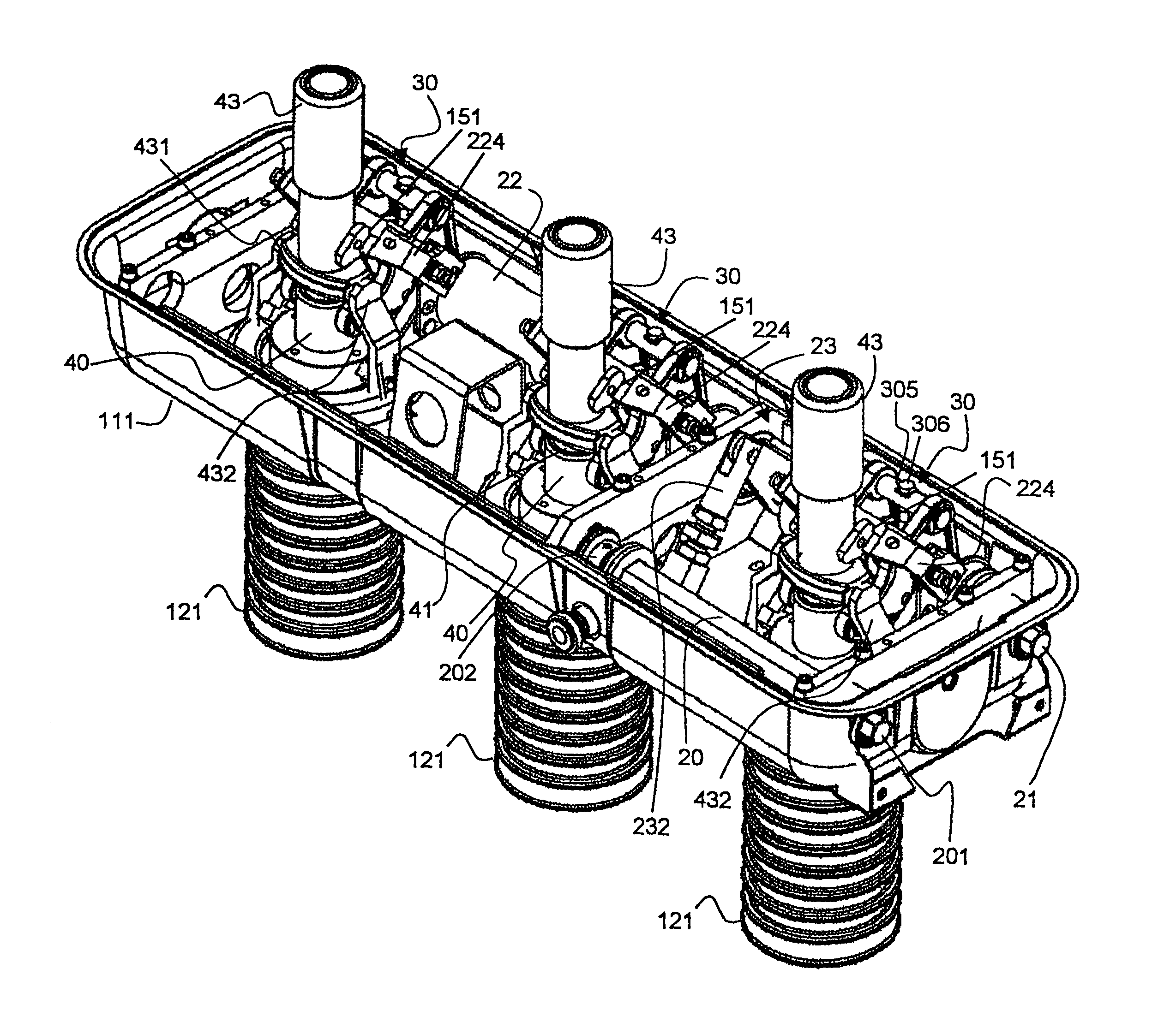
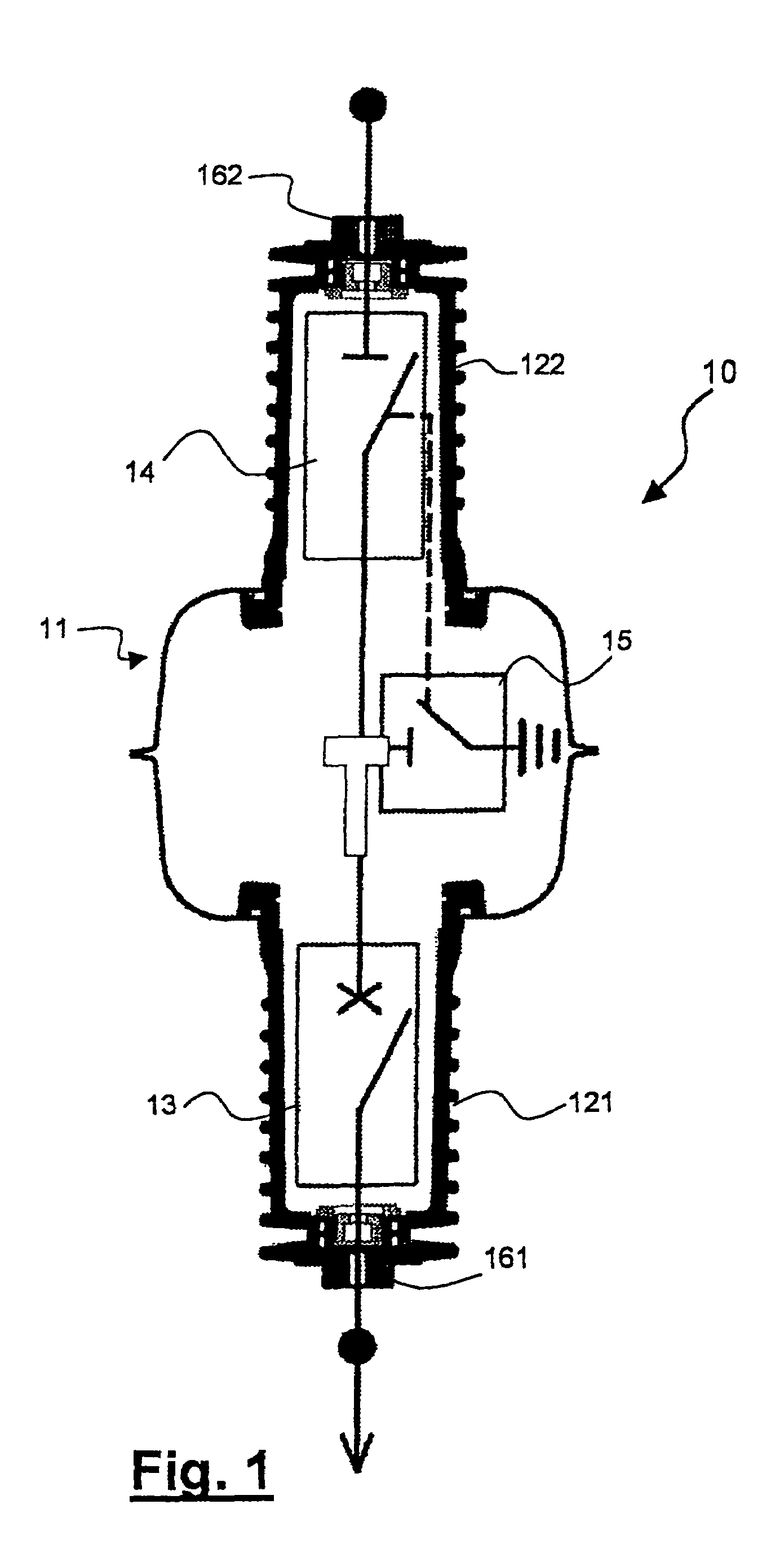
[0055]FIG. 1 shows schematically a three-phase device 10 according to the present invention. Obviously, the device 10 could also be two-phase or single-phase instead of three-phase. A three-phase device is described solely by way of a non-limiting example. The three-phase device 10 according to the present invention comprises a first shell 111 and a second shell 112 which can be joined together and sealingly welded along respective contact edges so as to form, overall, a casing 11. Preferably, the casing 11 is made of steel and the empty spaces inside it are filled with gas, typically sulphur hexafluoride (SF6), nitrogen, a mixture thereof or any other inert gas. Nitrogen is deemed the best for containing environment pollution.

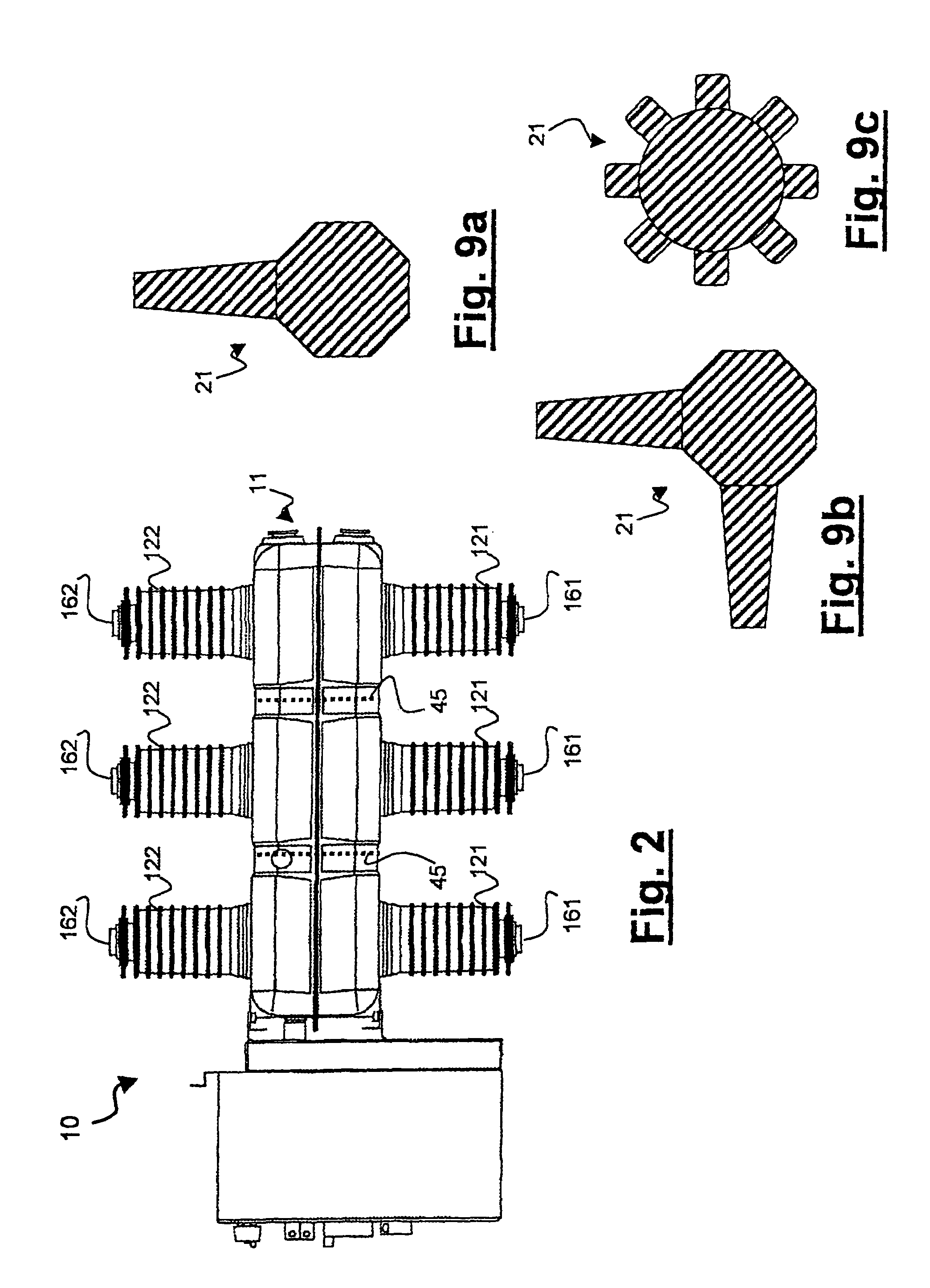
[0056]Three insulating bodies 121, 122 (one for each phase of the three-phase device) extend from the first and second shells 111, 112, resulting in a total of six substantially mutually facing insulating bodies (FIG. 2). Typically, the insulating bodies are m...


PUM


Abstract

An electric device, in particular for medium or high voltage electric substations, able to perform the functions of circuit-breaking, isolating and earthing is described. The device comprises: a casing; at least one circuit-breaker; at least one line isolator having a fixed isolator contact; a line isolator actuating shaft for actuating the at least one line isolator; at least one earthing isolator; a circuit-breaker actuating shaft for actuating at least one circuit-breaker; and a lever connected to a conductor rod co-operating with movable circuit-breaker contacts, said conductor rod further engaging with said fixed isolator contact in a closing position, wherein: the device further comprises a resilient member co-operating with said conductor rod in order to transfer correct pressing loads to said movable contacts. According to the invention, said circuit-breaker actuating shaft and said line isolator actuating shaft are coaxial. Profitably, the casing is filled with nitrogen or sulphur hexafluoride.

Description

[0001]This application is based on, and claims the benefit of, Italian Patent Applications Nos. MI2003A002355, MI2003A002356, MI2003A002357, MI2003A002358, MI2003A002359 all filed on Dec. 2, 2003, which are all incorporated by reference herein.BACKGROUND[0002]1. Field of the Invention[0003]The present invention relates to an electric device, in particular for medium or high voltage electric substations, able to perform the functions of circuit-breaking, isolating and earthing. In other words, the invention relates to a device suitable for installation in cubicles of the protected type which form medium or high voltage electric switchboards. According to one embodiment, the device of the invention has a resilient member for transferring correct pressing loads to the circuit-breakers. Furthermore, in the device according to one embodiment of the invention, a circuit-breaker actuating shaft and a line isolator actuating shaft are coaxial.[0004]2. Related Art and Other Considerations[00...

Claims


Application Information

Patent Timeline
Patent Type & Authority Patents(United States)
IPC IPC(8): H01H9/40H01H1/50H01H31/00H01H33/02H01H33/12H01H33/66H01H33/666
CPCH01H33/6661H01H33/125H01H1/50H01H31/003H01H33/022
Inventor VAGHINI, ALBERTOPERLI, GIORGIOROSSI, ARMANDO
Owner AREVA T&D ITAL
Why Eureka
Try Eureka