Eureka AIR delivers breakthrough ideas for toughest innovation challenges, trusted by R&D personnel around the world.

Compression brace material with spacer fabric inner layer

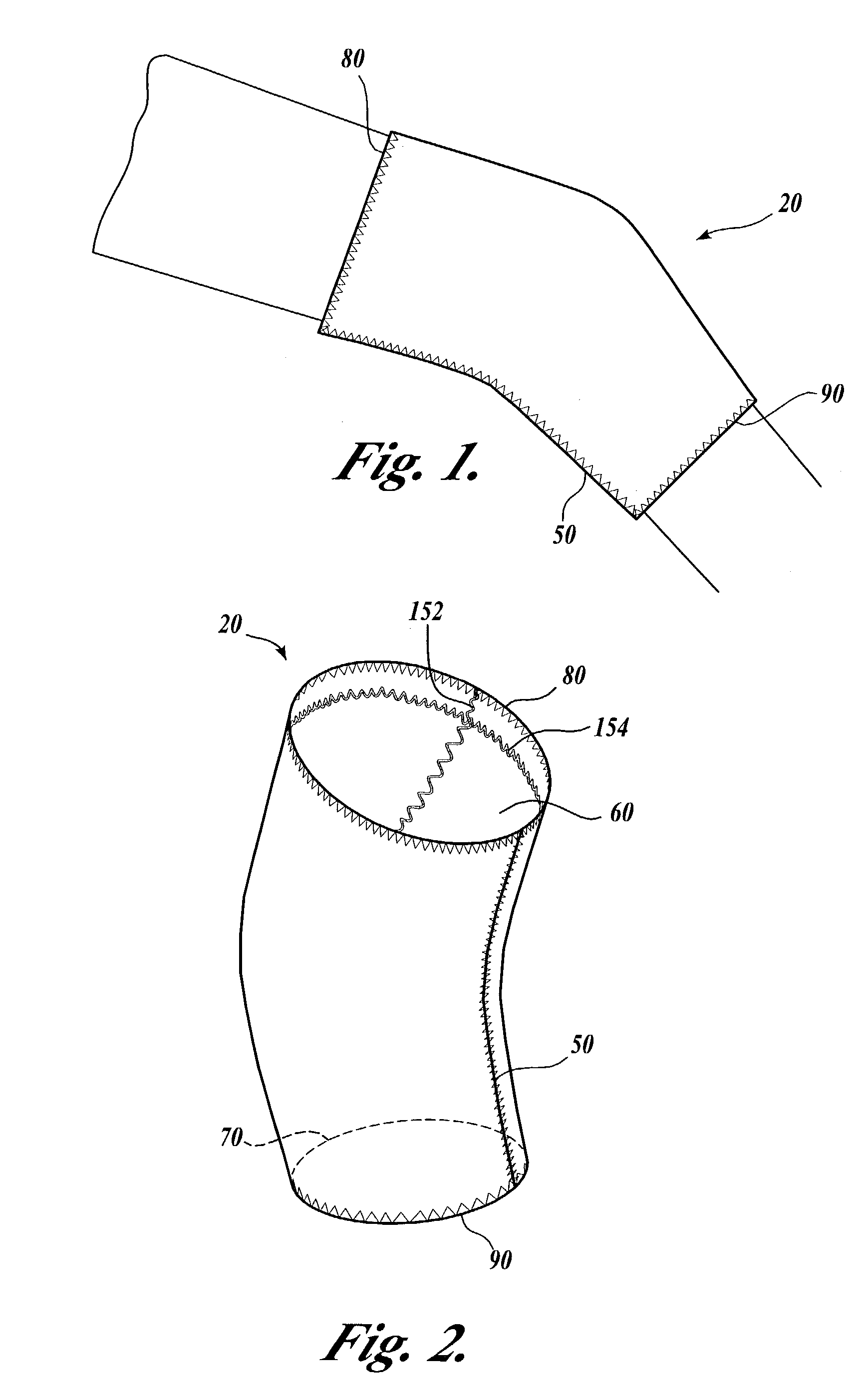
a compression brace and inner layer technology, applied in the field of orthopaedic supports, can solve the problems of heat dissipation very well, heat discomfort and perspiration, and the user's problems,

Inactive Publication Date: 2006-08-15
LA POINTIQUE INT
View PDF37 Cites 54 Cited by
  • Summary
  • Abstract
  • Description
  • Claims
  • Application Information

AI Technical Summary

Benefits of technology

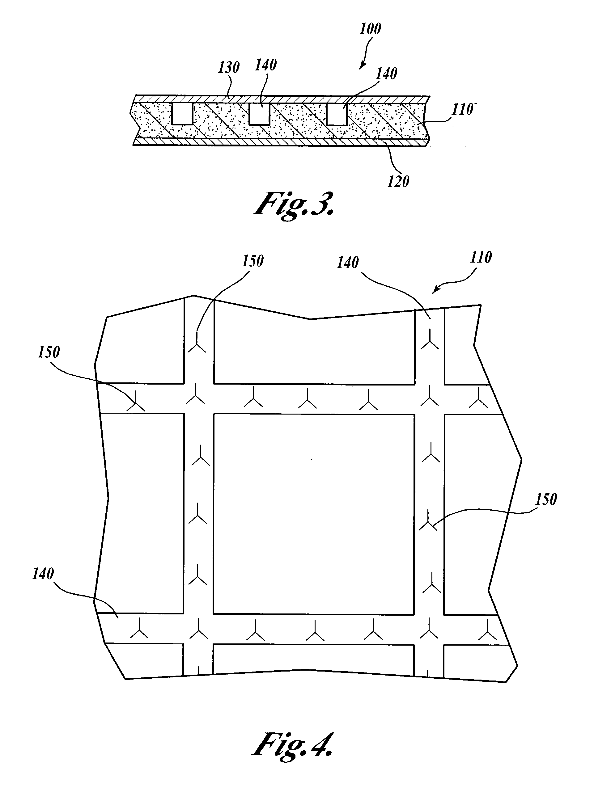
[0010]An embodiment of the present invention provides a flexible, resilient composite material for use in forming elastic compression braces for surrounding and supporting a body part by compression. The composite material includes a center elastic layer, an inner fabric layer, and an outer fabric layer. The elastic center layer is preferably composed of closed cell material in sheet form, having on one side thereof a plurality of grooves or channels formed therein to intersect each other to define a gridwork. The pattern of channels provides passageways along the width and length of the center layer to enable heat and moisture dissipation for the body part being supported.
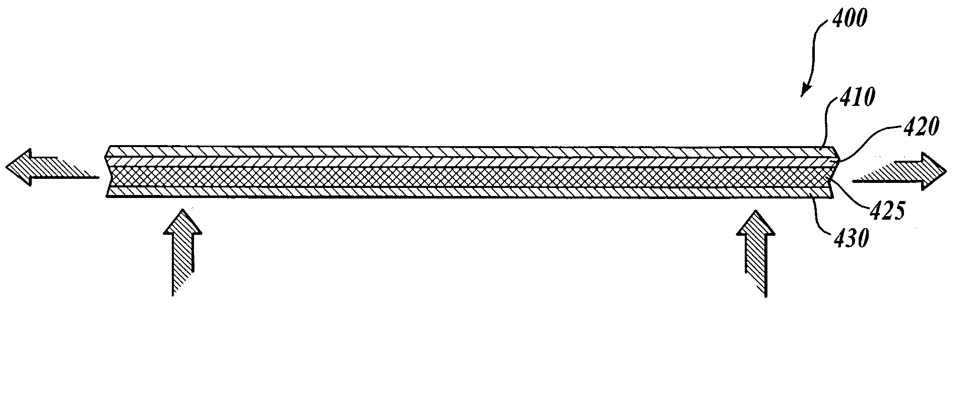
[0014]In another embodiment of the invention, the composite material includes an elastic outer layer, a first fabric layer, a spacer fabric layer, and a second fabric layer. The spacer fabric layer provides a lightweight component that permits airflow laterally through the composite material.

Problems solved by technology

Polychloroprene rubber is a closed cell material and therefore does not dissipate heat very well during use.
Although use of polychloroprene rubber in elastic compression braces can concentrate heat, the natural tendency of the closed cell material to prevent heat dissipation may cause problems for the user.
This compression fit, combined with the high density of the material and the lack of air circulation and dissipation through the material, can result in heat discomfort and perspiration, and may lead to heat rashes.
Prolonged use of such braces can cause the user to perspire constantly, resulting in discomfort to such a ° that the user often stops wearing the brace prematurely.
However, these braces may not retain sufficient structural integrity to serve as an effective compression brace for the wearer because neoprene material is removed from these braces.

Method used


Image

  • Compression brace material with spacer fabric inner layer
  • Compression brace material with spacer fabric inner layer
  • Compression brace material with spacer fabric inner layer

Examples


third embodiment

[0053]FIG. 10 illustrates a center layer 210 for a composite material in accordance with the present invention. In this embodiment, the center layer 210 is provided with a plurality of arcuate slits 250 that extends entirely through the thickness of the center layer 210. The arcuate slits 250 are preferably semi-circular or partially circular slits defining approximately 180° to 270° of a full circle. The arcuate slits 250 define a plurality of tab portions 255 that remain hingedly attached to the center layer 210, but that can open to allow airflow through the center layer 210. The curved geometry of the slits 250 provides a relatively long slit in a relatively short transverse distance on the center layer 210.

[0054]The plurality of arcuate slits 250 is arranged in a rectangular, offset array, as shown in FIG. 10. The center layer 210 is preferably between about 1.5 mm and about 8 mm thick and, most preferably, about 3 mm thick. The arcuate slits 250 have a diameter D that is prefe...

fourth embodiment

[0058]A center layer 310 for the present invention is shown in FIG. 12, wherein a center layer 310 substantially identical to the center layer 210 (shown in FIG. 11) is provided with a plurality of elongate, shallow grooves or channels 340 that extends laterally across the inner face of the center layer 310. As discussed in detail above, the network of intersecting grooves 340 provides channels that promote airflow adjacent the wearer's skin, along the inner face of the composite material. As seen most clearly in FIG. 13, which shows a cross-sectional view of the center layer, the slits 350 are preferably positioned directly adjacent or intersecting the grooves 340, so that air and vapor are directed towards the slits 350; or conversely, air entering from the slits is directed toward the grooves 340.

[0059]FIGS. 14 and 15 show a cross section of a composite material 300 utilizing the center layer 310. The composite material 300 includes an elastic inner fabric layer 330, preferably a...


PUM

PropertyMeasurementUnit
thicknessaaaaaaaaaa
thickaaaaaaaaaa
thickaaaaaaaaaa

Abstract

The present invention provides a composite material for use in making orthopedic elastic braces for supporting a body part by compression. One embodiment of the invention is a compression brace material (400) having an elastic outer layer (410), a first fabric layer (420), a spacer fabric layer (425), and a second fabric layer (430). The spacer fabric layer permits and promotes airflow laterally through the brace material. The outer layer may have a plurality of slits (550) therethrough to permit and promote airflow transversely through the composite material. The plurality of slits may be arcuate to further improve transverse airflow through the composite brace material.

Description

CROSS-REFERENCE TO RELATED APPLICATIONS[0001]This is a continuation-in-part of prior U.S. patent application Ser. No. 10 / 004,469, filed Oct. 23, 2001 now U.S. Pat. No. 6,726,641, which is itself a continuation-in-part of U.S. patent application Ser. No. 09 / 846,332, filed May 2, 2001 now U.S. Pat. No. 6,508,776, priority from the filing date of which is hereby claimed under 35 U.S.C. § 120.FIELD OF THE INVENTION[0002]This invention generally relates to orthopedic supports and, more specifically, to a composite material for use in making elastic compression braces having improved compression support, body heat retention, and breathability during use.BACKGROUND OF THE INVENTION[0003]Elastic compression braces are available in many forms. Commonly, such braces are composed of soft, elastic material so that when worn, they provide a certain amount of support for an injured joint. These types of braces, often purchased without a prescription or the need for skilled professional fitting, h...

Claims


Application Information

Patent Timeline
Patent Type & Authority Patents(United States)
IPC IPC(8): A61F5/00A61F5/01A61F13/04A61F5/02A61F13/00A61F13/06A61L15/00B32B1/08B32B3/30B32B5/04B32B5/18B32B5/32B32B25/04
CPCA61F5/01A61F5/0104A61F13/061B32B1/08B32B25/04B32B5/04B32B5/18B32B5/32B32B3/30A61F13/04A61F13/06A61F13/101A61F5/0109B32B5/02B32B5/026B32B5/06B32B5/245B32B5/26B32B7/12B32B15/02B32B2262/0261B32B2266/0228B32B2266/08B32B2307/51B32B2307/546B32B2307/732B32B2535/00B32B5/028
Inventor CHIANG, JACKSONCHUANG, JONATHON
Owner LA POINTIQUE INT
Why Eureka
Eureka Blog
Learn More