Power transmission device
a power transmission device and power transmission technology, applied in the direction of marine propulsion, vessel construction, gearing, etc., can solve the problems of complex structure and increase weight, and achieve the effect of simple and light structure, preventing mutual interference between the drive force for rotation and the drive force for turning
- Summary
- Abstract
- Description
- Claims
- Application Information
AI Technical Summary
Benefits of technology
Problems solved by technology
Method used
Image
Examples
embodiment 1
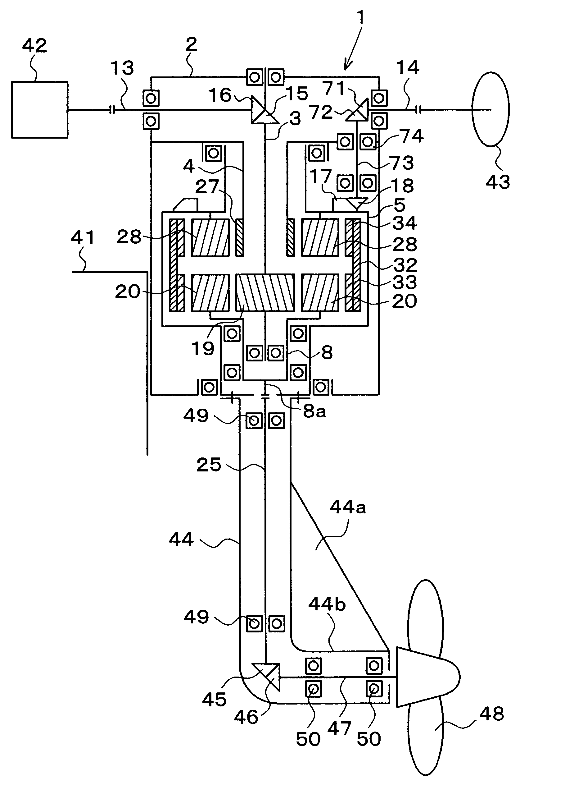
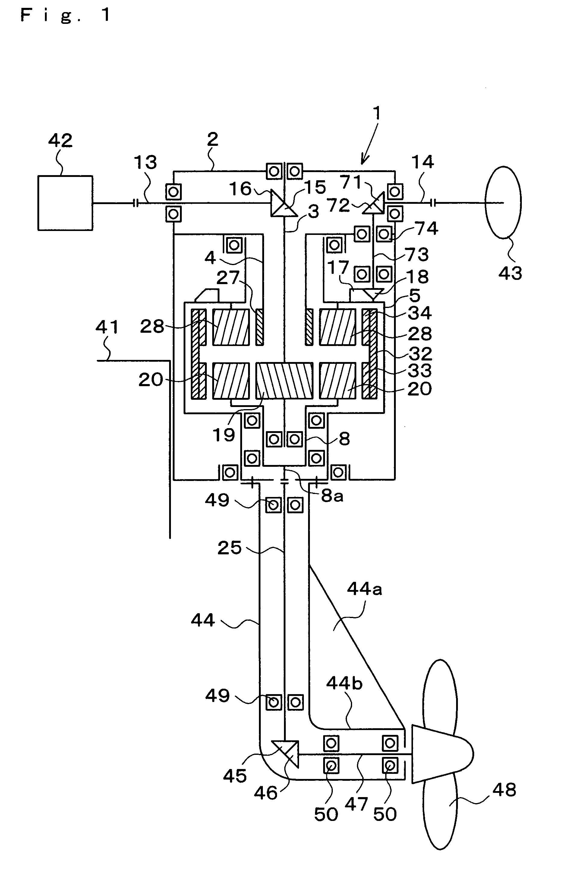
[0038]Embodiments of the invention are described in the following with reference to the accompanying drawings. In a power transmission device 1 of Embodiment 1, as shown in FIG. 1 to FIG. 4, a transmission shaft 3 is disposed at the center of a housing 2, and a turning body 5 is arranged on the outer side of the transmission shaft 3 through a hollow-cylindrical shaft 4. The turning body 5 is supported at the housing 2 by bearings 6 and 7, and a cup-shaped rotating body 8 is supported on the inner side of the lower end portion of the turning body 5 by a bearing 9. The transmission shaft 3 is almost inserted into the inner side of the turning body 5, and has its lower end supported at the rotating body 8 by a bearing 11 and its upper end supported at the housing 2 by a bearing 10. As a result, the transmission shaft 3 and the turning body 5 are supported at the housing 2 so as to be relatively coaxially rotatable. The hollow-cylindrical shaft 4 is inserted into the inner side of the t...
embodiment 2
[0052]Here is described another application example of the power transmission device 1. In this application example shown in FIG. 9, the power transmission device 1 is incorporated into a 2WD motorcycle or bicycle. Accordingly, the power transmission device 1 of Embodiment 2 shown in FIG. 9 is different in the supporting structure of the rotating input shaft 13 and in the input type for turning from the power transmission device 1 of Embodiment 1. Specifically, the transmission shaft 3 protrudes to the outside of the housing 2, and the rotating input shaft 13 is connected to that protruding portion through the bevel gears 15 and 16. The rotating input shaft 13 may or may not be supported by the housing 2. This housing 2 is fixed on a body frame 51; the turning body 5 is mounted on a front wheel fork 52; and the output shaft 25 and a front wheel drive shaft 53 acting as the rotating shaft are supported at the casing 44. The drive force for rotation by the engine or the pedal (althoug...
embodiment 3
[0054]In an application example shown in FIG. 10, the power transmission device 1 is incorporated into the oscillating mechanism of a wind power generating system. Accordingly, the power transmission device 1 of Embodiment 3 shown in FIG. 10 is different in the following points from the power transmission device 1 of Embodiment 1. Specifically: the housing 2 is fixed on a post 61 in a mode inverted from that of the case of the ship propelling mechanism; the rotating input shaft 13 is connected to an input portion 8b of the rotating body 8; and the output shaft 25 is connected to the lower end of the transmission shaft 3. An oscillating head 62 is so mounted on the turning body 5 through the casing 44 as to turn in all directions; the rotating input shaft 13 is supported at the casing 44; and a propeller shaft 64 is supported at the oscillating head 62 by a bearing 67. The propeller shaft 64 is perpendicularly connected to the rotating input shaft 13 through bevel gears 65 and 66, an...
PUM
 Abstract
Description
Claims
Application Information
 - R&D
- Intellectual Property
- Life Sciences
- Materials
- Tech Scout
- Unparalleled Data Quality
- Higher Quality Content
- 60% Fewer Hallucinations
Browse by: Latest US Patents, China's latest patents, Technical Efficacy Thesaurus, Application Domain, Technology Topic, Popular Technical Reports.
© 2025 PatSnap. All rights reserved.Legal|Privacy policy|Modern Slavery Act Transparency Statement|Sitemap|About US| Contact US: help@patsnap.com


