Hybrid transmission

a hybrid transmission and transmission shaft technology, applied in the direction of electric propulsion mounting, transportation and packaging, gearing, etc., can solve the problems of deterioration of the mounting strength of the hybrid transmission, lack of rigidity of the entire hybrid transmission, and so as to achieve the effect of deterioration of the installation ability of the hybrid transmission to the vehicle body, lack of rigidity of the entire hybrid transmission, and deteriora

Active Publication Date: 2006-08-15
NISSAN MOTOR CO LTD +1
View PDF16 Cites 6 Cited by
  • Summary
  • Abstract
  • Description
  • Claims
  • Application Information

AI Technical Summary

Benefits of technology

[0003]However, in the above-described related art having the two axially arranged motor / generators, an axial dimension of the hybrid transmission is increased, whereby installation ability thereof to a vehicle body will be deteriorated. Further, in the axial arrangement of the two motor / generators, the amount of overhang of one motor / generator unit which is disposed away from the prime power source is increased and supported in the form of a cantilever. This causes deterioration of the mounting strength of the hybrid transmission, thereby resulting in lack of rigidity of the entire hybrid transmission.
[0004]It is an object of the present invention to provide a hybrid transmission capable of preventing deterioration of installation ability thereof to a vehicle body which will be caused due to an increased axial dimension thereof, and suppressing the deterioration of the mounting strength which will be caused due to the cantilever supporting structure of one of the motor / generator unit, to thereby avoid the lack of the rigidity of the hybrid transmission.

Problems solved by technology

However, in the above-described related art having the two axially arranged motor / generators, an axial dimension of the hybrid transmission is increased, whereby installation ability thereof to a vehicle body will be deteriorated.
This causes deterioration of the mounting strength of the hybrid transmission, thereby resulting in lack of rigidity of the entire hybrid transmission.

Method used


Image

  • Hybrid transmission
  • Hybrid transmission
  • Hybrid transmission

Examples


Embodiment Construction

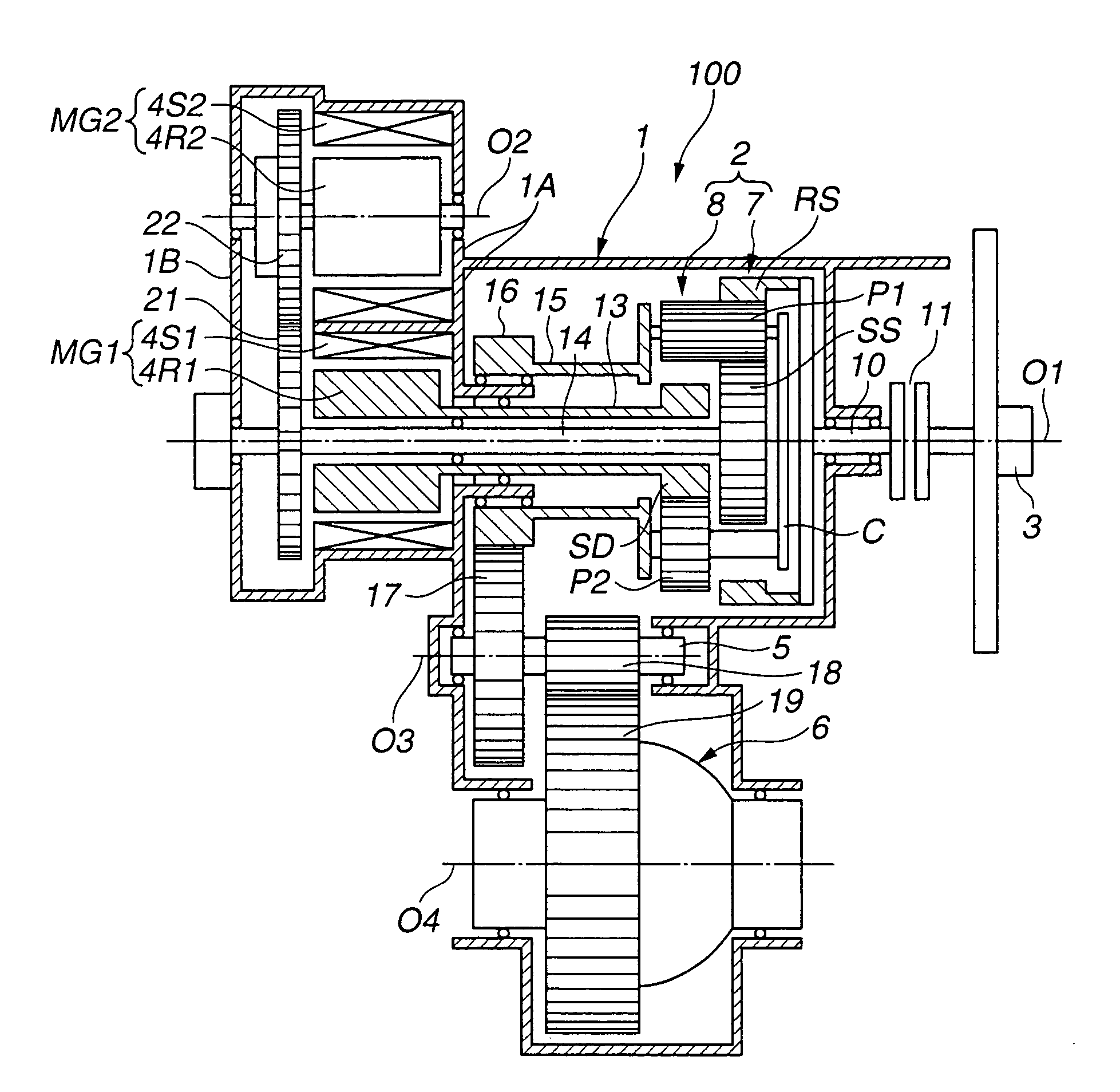
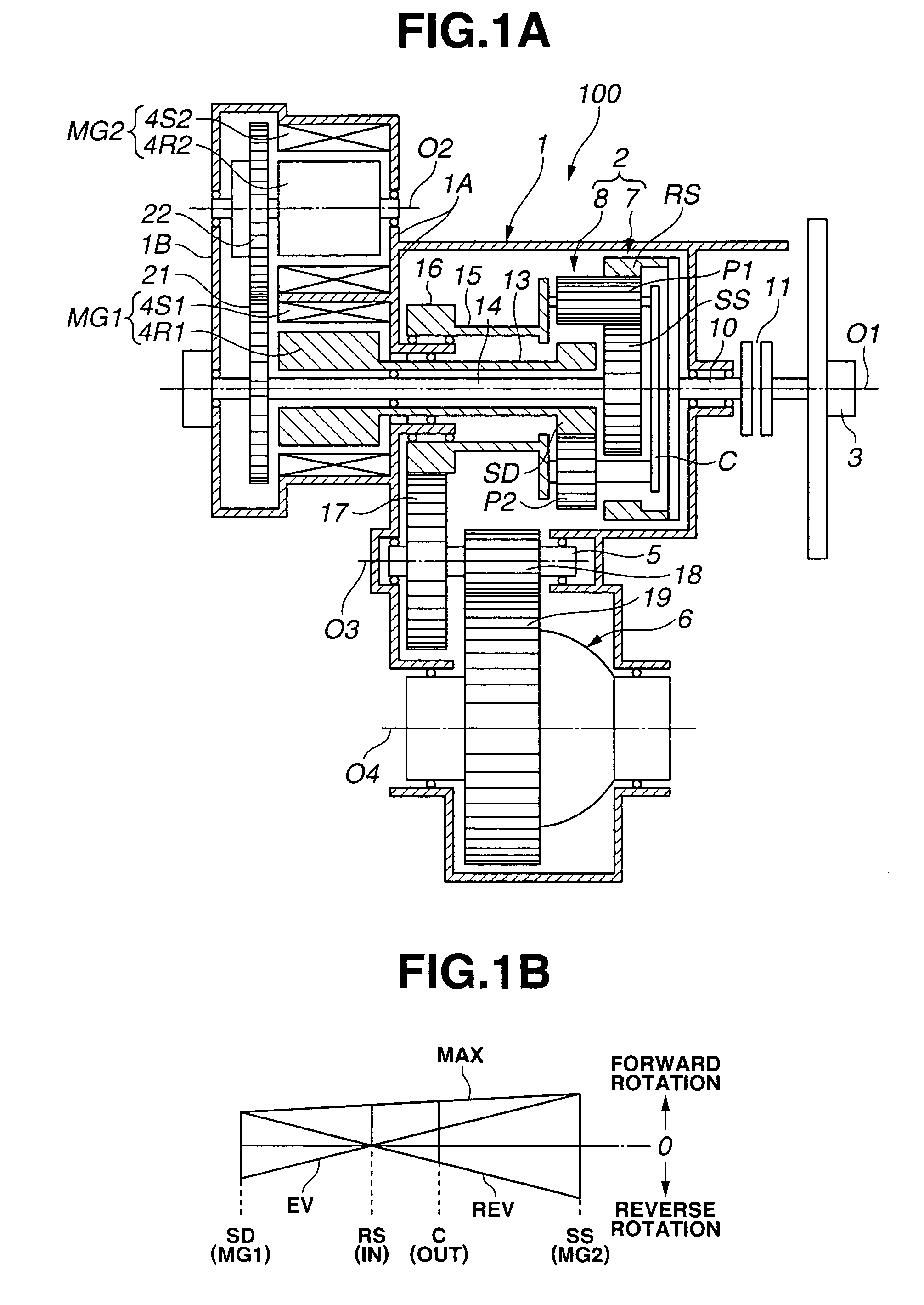
[0027]Referring to FIG. 1A, a hybrid transmission according to a first embodiment of the present invention now is explained. In this embodiment, the hybrid transmission is applied to a transaxle for a front-engine front-drive (FF) vehicle.

[0028]Hybrid transmission 100 includes transmission case 1 through which axis O1 extends, two degree-of-freedom gear mechanism 2, first motor / generator MG1 and second motor / generator MG2 which are installed in transmission case 1 along axis O1. As illustrated in FIG. 1A, two degree-of-freedom gear mechanism 2 is disposed on the right side as viewed in the figure in a direction of axis O1, and first and second motor / generators MG1 and MG2 are disposed on the left side as viewed in the figure in the direction of axis O1. Engine 3 acting as a prime power source is disposed on the outside of transmission case 1 and located on the right side of two degree-of-freedom gear mechanism 2 as shown in FIG. 1A. In FIG. 1A, there is shown only a crankshaft of en...


PUM


Abstract

A hybrid transmission connected with a prime power source, including an input member for receiving power input from the prime power source, a two degree-of-freedom gear mechanism having a first axis and including at least four rotating members that are associated to rotate about the first axis, a first motor / generator having a second axis aligned with the first axis of the two degree-of-freedom gear mechanism, and a second motor / generator having a third axis offset from and parallel to the first axis. The first motor / generator is drivingly connected with the first rotating member of the two degree-of-freedom gear mechanism. The second motor / generator is drivingly connected with the second rotating member of the two degree-of-freedom gear mechanism.

Description

BACKGROUND OF THE INVENTION[0001]The present invention relates to a hybrid transmission adapted for a hybrid electric vehicle (HEV) in which multiple power sources including an engine and a motor are provided. More specifically, the present invention relates to a hybrid transmission capable of continuously and variably transmitting the power output from the power sources using a differential device such as a planetary gear set.[0002]U.S. Pat. No. 5,935,035 (corresponding to Japanese Patent No. 3,330,900) discloses a hybrid transmission in which rotating members constituting a differential device are connected with a prime power source, a drive system and two motor / generators. The two motor / generators are arranged in an axial direction of the hybrid transmission.SUMMARY OF THE INVENTION[0003]However, in the above-described related art having the two axially arranged motor / generators, an axial dimension of the hybrid transmission is increased, whereby installation ability thereof to a...

Claims


Application Information

Patent Timeline
Patent Type & Authority Patents(United States)
IPC IPC(8): F16H3/72B60K1/02B60K6/365B60K6/445B60K6/547B60K17/04B60L50/16B60W10/10B60W20/00F16H3/62
CPCB60K6/365B60K6/445F16H3/727B60K1/02Y02T10/6239F16H2037/103F16H2200/2005F16H2200/2007B60L15/2054B60L2240/48B60L50/15Y02T10/62Y02T10/64Y02T10/7072Y02T10/72
Inventor YAMAUCHI, YASUHIROOSHIDARI, TOSHIKAZUKARGAR, KEYVANPICHON, YVES
Owner NISSAN MOTOR CO LTD
Why Eureka
Try Eureka