Fly fishing rod having a detachable reel seat and waist holder therefore

a fly fishing rod and reel seat technology, applied in the field of fly fishing rods, can solve the problems of deterring the overall enjoyment of fly fishing casting activity, unable to overcome the resistance of air friction, and very light weight of artificial lures or flies used, and achieve the effect of trouble-free operation

Inactive Publication Date: 2006-08-15
BORGEAT LOUIS
View PDF79 Cites 22 Cited by
  • Summary
  • Abstract
  • Description
  • Claims
  • Application Information

AI Technical Summary

Benefits of technology

[0025]Another advantage of the present invention resides in that the proposed fly fishing rod and associated waist holder is specifically designed so as to be manufacturable using conventional forms of manufacturing thus providing a fly fishing rod and associated waist holder which will be economically feasible, long lasting and relatively trouble free in operation.
[0026]According to a general aspect, there is provided a fishing rod which comprises a fishing rod shaft having a primary reel seat and at least one guiding eyelet extending from the fishing rod shaft for guiding a fishing line along the fishing rod shaft; a hollow cylinder having an outer surface, a longitudinal cavity defined therein, and a cylinder mounting foot protruding outwardly from the outer surface, the cylinder mounting foot being juxtaposed to and releasably engaged with the primary reel seat for mounting the hollow cylinder to the fishing rod shaft; and an auxiliary reel seat having a reel mounted thereto through a reel mounting foot, at least a portion of the auxiliary reel seat being releasably and slidably inserted into the cavity of the hollow cylinder with the reel extending outwardly therefrom, the at least one guiding eyelet guiding a fishing line from the reel along the fishing rod shaft by receiving the fishing line therethrough.
[0027]According to another general aspect, there is provided a fishing rod comprising a fishing rod shaft with a primary reel seat and at least one guiding eyelet extending from the fishing rod shaft; a hollow cylinder having a cylindrical wall defining a longitudinal cavity, an outer surface and an insertion opening, the hollow cylinder having a cylinder mounting foot extending outwardly from the outer surface of the cylindrical wall, the cylinder mounting foot being releasably engaged with the primary reel seat for mounting the hollow cylinder to the fishing rod shaft; and an auxiliary reel seat releasably and slidably inserted into the longitudinal cavity of the hollow cylinder, the auxiliary reel seat having a reel mounted thereon, the reel extending outwardly through the insertion opening, the at least one guiding eyelet guiding a fishing line from the reel along the fishing rod shaft by receiving the fishing line therethrough.
[0028]According to a further general aspect, there is provided a fishing rod comprising: a fishing rod shaft with a reel seat mounted to the fishing rod shaft; a hollow cylinder having a cylindrical wall defining an outer surface, a longitudinal cavity therein and an insertion opening therein, a cylinder mounting foot protruding outwardly from the outer surface, and a coil spring disposed inside said hollow cylinder at a closed end thereof, the cylinder mounting foot being releasably engaged with the reel seat for mounting the hollow cylinder to the fishing rod shaft; and a reel and reel seat assembly having a reel mounted to an auxiliary reel seat through a reel mounting foot, at least a portion of the auxiliary reel seat being releasably and slidably inserted into the cavity of the hollow cylinder with the reel extending outwardly therefrom through the insertion opening, said coil spring being compressed when the at least a portion of the auxiliary reel seat is inserted inside said hollow cylinder.

Problems solved by technology

Conversely, in fly casting the artificial lures or flies used are very light weight and not capable of causing the rod to flex.
In fact, the lures are so light weight that the resistance due to air friction cannot be overcome unless the fly is attached to a heavier object.
First, with each cast, the fisherman's arm has to transmit to the rod the energy required to send the line the required distance.
These subtle movement adjustments in a somewhat non-ergonomic position may quickly lead to muscle fatigue which, in turn, may deter the overall enjoyment of the fly fishing casting activity.
Furthermore, as the infrequently solicited muscles of the hand, wrist and arm become tired, the efficiency of the casting stroke will be lessened.
But progress in this latter area has become less and less a factor in the search for lightness; in the end, it has provided limited improvement since a great portion of the weight resides in the reel and associated reel seat.
Prior art rod holders have been utterly unamenable to use with a fly rod, instead being configured to accommodate general-purpose rod and reel.
This sort of holder will not work when used with a fly rod.
Hence, the prior art rod holder simply will not work satisfactorily with a fly rod.
Furthermore, the idea of inserting the rod into a holder to take some weight off the fisherman does not work for fly fishing rods.
Indeed, once the rod is in its holder, it becomes practically immobile, which is hardly compatible with a fishing style that involves repeated casts.
One of the main disadvantages associated with this invention resided in that only the reel is separable from the rod.
This operation can prove to be both tedious and time consuming.

Method used


Image

  • Fly fishing rod having a detachable reel seat and waist holder therefore
  • Fly fishing rod having a detachable reel seat and waist holder therefore
  • Fly fishing rod having a detachable reel seat and waist holder therefore

Examples


first embodiment

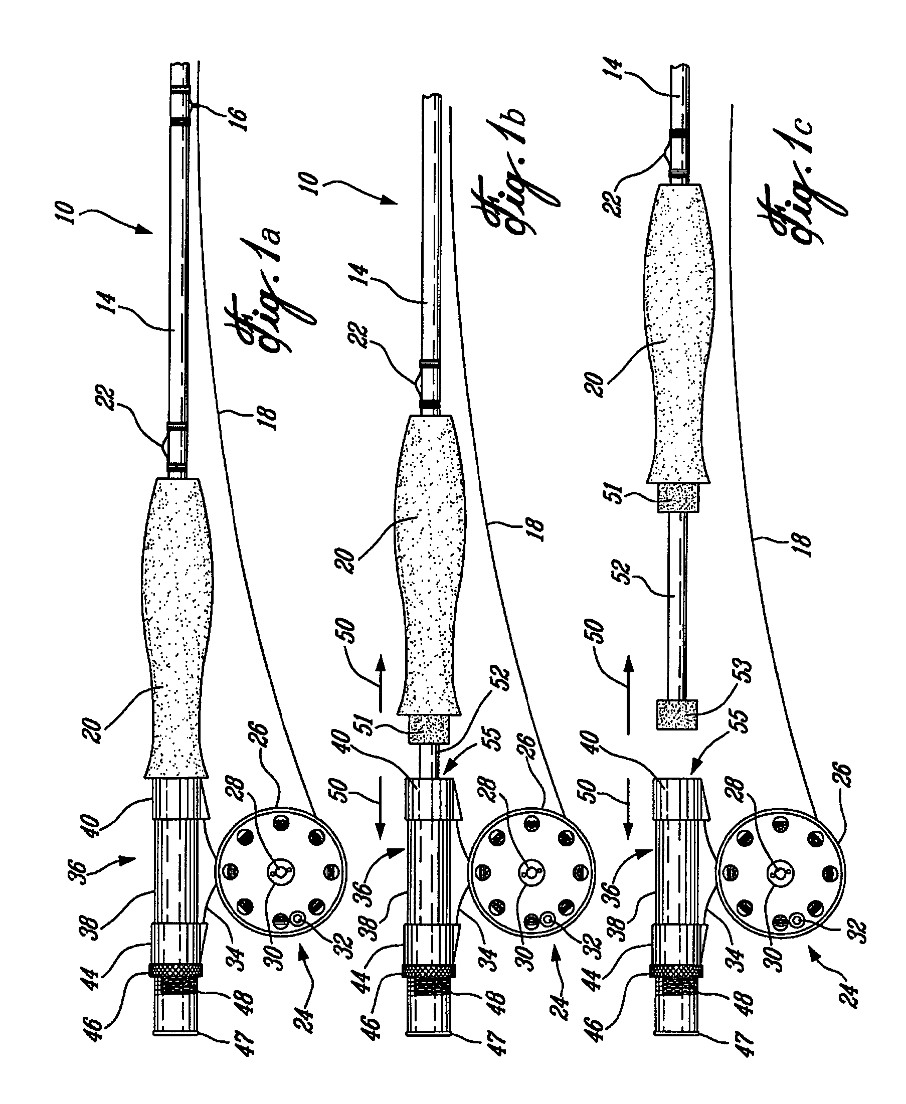
[0035]Referring to FIG. 1, it is shown a fly fishing rod 10 in accordance with the present invention.

[0036]The fishing rod 10 is preferably of the fly fishing type. The fishing rod 10 includes an elongated rod shaft 14 (only a butt section thereof being shown). A set of guiding eyelets 16 (only one of which is shown) are mounted on the rod shaft 14 for guiding a fly line 18 there along.

[0037]Typically, although by no means exclusively, the rod shaft 14 includes a tip section releasably attached to the butt section by a male / female ferrule combination as is well known in the art. The proximal end of the butt section part of the rod shaft 14 is attached to a general cylindrical handgrip 20. A keeper ring 22 is preferably mounted on the rod shaft 14 adjacent the hand grip 20.

[0038]The fishing rod 10 else includes a conventional fly reel 24 for winding the fly line 18. The fly reel 24 typically includes a spool 26 rotatably mounted on a reel frame by an axle 28 and having a drag 30 atta...

second embodiment

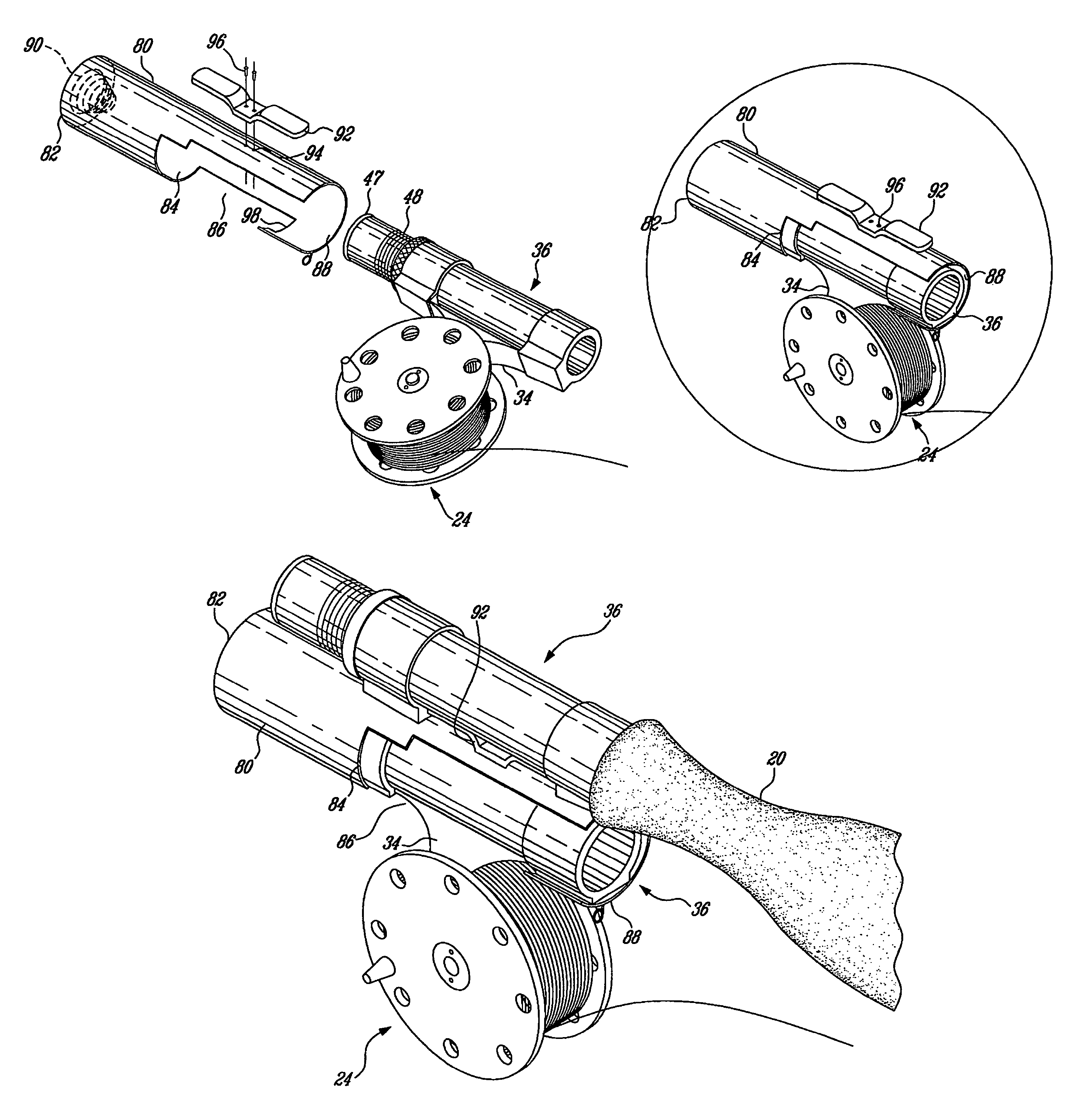
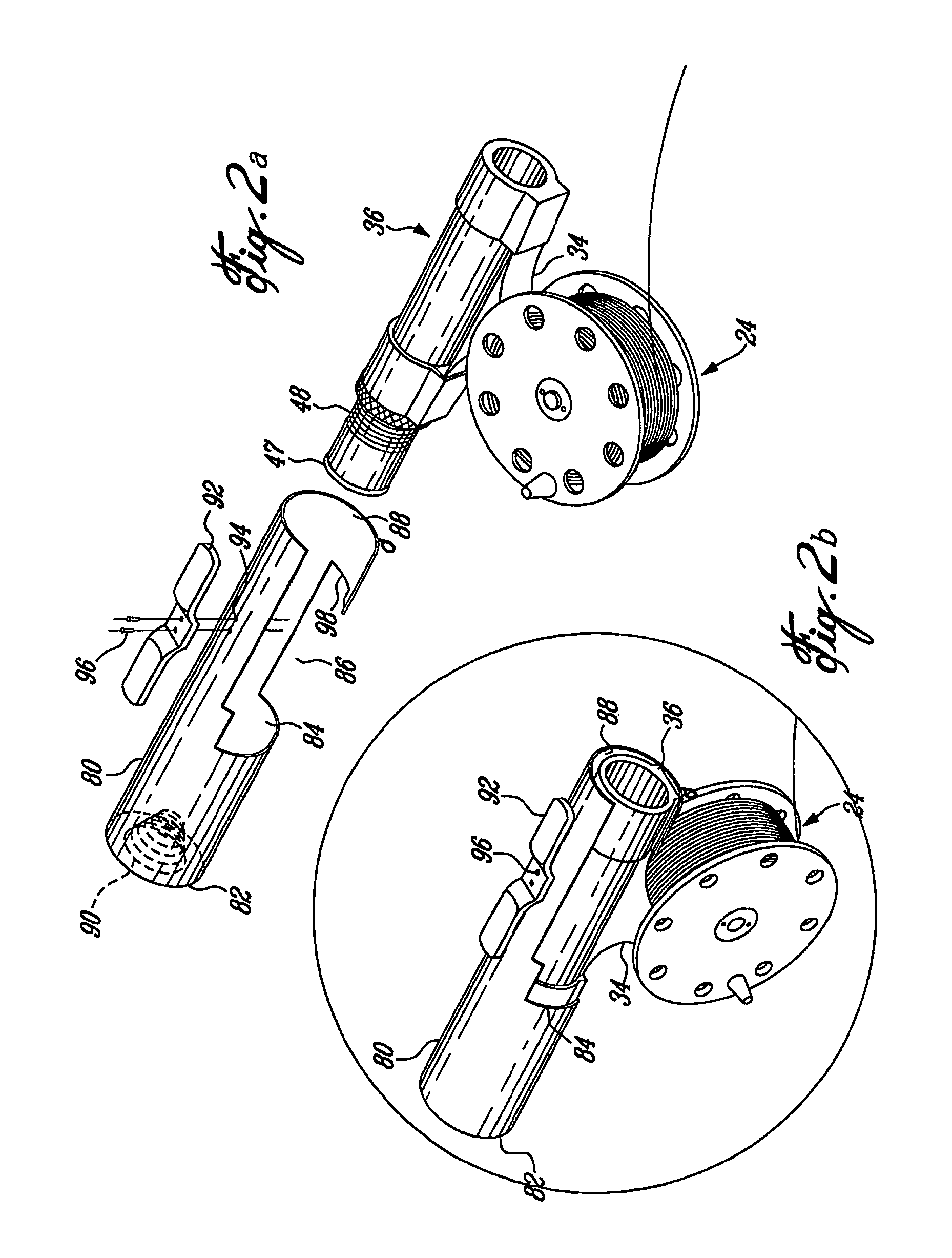
[0044]FIG. 2 presents the invention, namely the device used to hold or release an additional reel seat 36 accompanying any conventional fly fishing rod 10.

[0045]The main part of this device is a hollow cylinder 80 that is preferably made of metal or plastic. This cylinder 80 is closed at its proximal end 82, partially open on one of its sides 84 and its lower part 86, and fully open at its distal end 88.

[0046]Inside the cylinder 80, at the closed end 82, is a coil spring 90 in the form of a cone. At the middle of the topside of the cylinder 80, a mounting foot 92 is attached in two holes 94, preferably with rivets or bolts 96. This mounting foot 92 is used to attach the cylinder 80 to the reel seat 36 of the fly fishing rod 10. The mounting foot 92 is somewhat similar in its form, and wholly identical in its function, to the mounting foot 34 used to attach a reel 24 to a reel seat 36.

[0047]The purpose of the cylinder 80 is to hold a reel seat 36, equipped with a reel 24, in such a w...


PUM


Abstract

The present invention concerns a reel seat holding device for a movable reel and reel seat assembly for fly fishing rods. The holding device comprises a case that is arranged for releasably receiving the reel seat therein, when the reel and reel seat assembly is detached from a fly fishing rod. A device is provided for mounting the case on a fishing rod or an holder. The disclosure of the present invention also relates to a fly fishing rod with a movable reel and reel seat assembly and a waist holder for the holding device.

Description

CROSS-REFERENCES[0001]This application is a divisional of patent application Ser. No. 09 / 882,092 filed on Jun. 18, 2001 now abandoned, currently pending and which is hereby incorporated by reference in its entirety.FIELD OF THE INVENTION[0002]The present invention relates to the general field of fly-fishing and is particularly concerned with a fly fishing rod having a detachable reel seat and waist holder therefore. More particularly, the present invention relates to a reel seat holding device for a movable reel and reel seat assembly for fly fishing rods.BACKGROUND OF THE ART[0003]During most sport fishing activities such as fly casting, spin casting, bait casting and the like, an artificial lure or a live bait having a fishing line attached thereto is projected or cast into fish filled waters in hope that a fish will take the bait. Since most fishes are quite easily scared away by human presence, it is often desirable to cast the bait far away from the fisherman.[0004]Typically, t...

Claims


Application Information

Patent Timeline
Patent Type & Authority Patents(United States)
IPC IPC(8): A01K87/00A01K87/06
CPCA01K87/06
Inventor BORGEAT, LOUIS
Owner BORGEAT LOUIS
Why Eureka
Try Eureka