
Tree harvesting apparatus and method which enable a cut top or other cut portion of a tree to be weighed before being dropped or lowered to the ground

a harvesting apparatus and tree technology, applied in the direction of tree debarking, agriculture, manufacturing tools, etc., can solve the problems of damage to structures, excessive handling time, and no way to measure the actual weight of a cut tree top, etc., and achieve the effect of safe weighing

Inactive Publication Date: 2006-08-08
BIG BEAVER WOOD COMPANY INC THE
View PDF16 Cites 20 Cited by
  • Summary
  • Abstract
  • Description
  • Claims
  • Application Information

AI Technical Summary

Benefits of technology

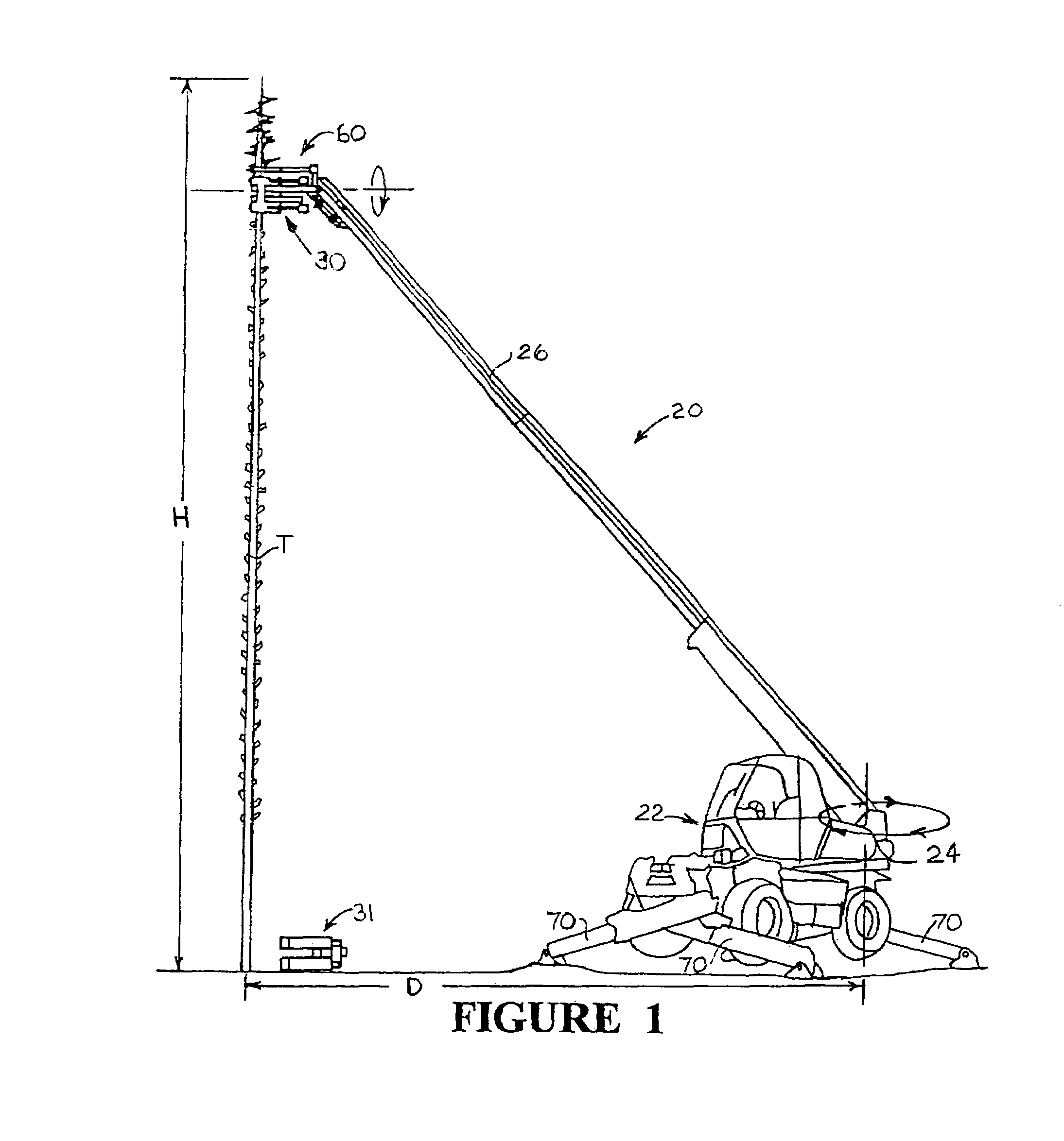
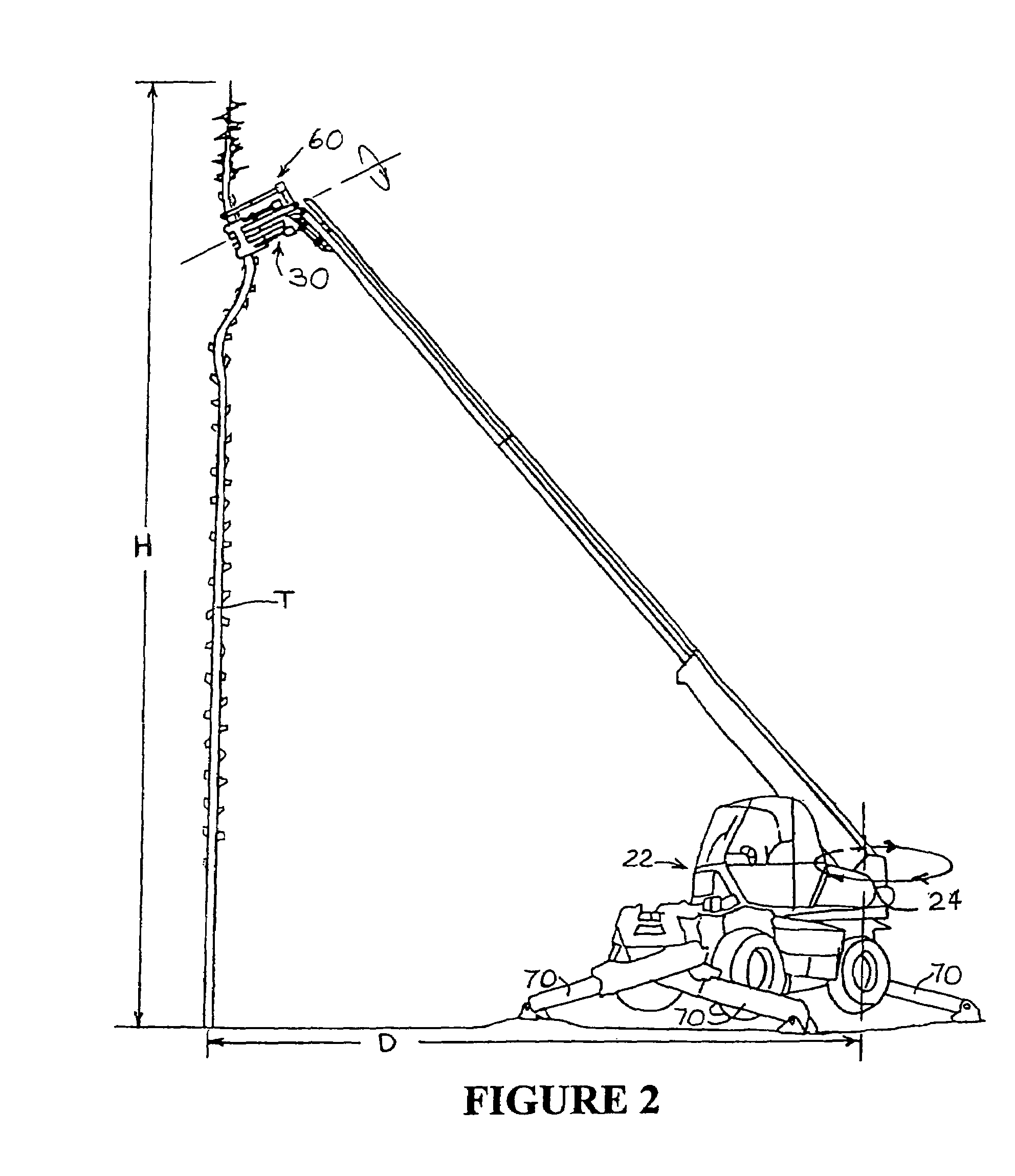
[0010]A tree harvesting apparatus and method, according to the invention, is based on providing a set of gripping arms and an associated cutting mechanism for gripping and cutting off the top and other portions of the tree in sequence. The harvesting apparatus is mounted at the outer end of a positionable boom that can be swung 360°. When the harvesting is being undertaken in crowded conditions or there is otherwise concern for handling the weight of the top or other cut portion, the invention apparatus enables the cut portion to be weighed immediately after being cut and the measured weight to be used as a basis for deciding whether to allow the cut portion to free fall or be lowered to the ground. Applicant has thus recognized the advantage of both being able to weigh a cut portion of a single tree during harvesting and of being able to rotate the boom 360° when harvesting and weighing portions of multiple trees in a single area accessible to the boom and to the tree harvesting apparatus mounted on the boom. Numerous cut portions of trees can thus be safely weighed and numerous trees can thus be harvested without having to relocate the vehicle on which the boom is mounted. A camera mounted on the boom near the harvesting apparatus is used to observe the manner in which the cut portion is weighed. In combination with being able to weigh a portion of a tree after being cut the invention also has the advantage through use of the camera which is aimed at the clamping and cutting apparatus of being able to monitor the weighing procedure and detect jams caused by oversized timber, metal debris and the like. Provision is also made for measuring with a computerized system the weight of the cut portion of the tree after taking into consideration and processing the existing Manitou apparatus computer signals representing the height of the tree being cut and the distance between the base of the tree and the base of the boom.

Problems solved by technology

Problems arise when the tree being harvested is in a suburban area and is close to a fence, house, shelter or the like, any of which might be struck and damaged when the cut tree top or other cut portion of the tree is believed to be unusually heavy and is released and allowed to free fall to the ground and risk damaging structures in its path.
Heretofore, there has been no way for measuring the actual weight of a cut tree top, a tree length, or block prior to its being dropped or lowered to the ground.
Excessive handling time thus becomes involved when the boom mounted cutting and gripping apparatus is used to lower a cut top, limb, short block, or other cut portion of a tree to the ground, even though the cut top, limb or block might otherwise be within a prescribed safe weight limit.
Risks are also taken when the actual weight of a cut top or other cut portion of a tree is so heavy as to overload the boom and cause it to tip over.
In none of the prior art practices however, has the operator been able to measure the actual weight of a tree top, limb or short block after it has been cut but before it has been dropped or lowered to the ground.
Overloading of the tree harvesting apparatus may and can occur with prior art practices.

Method used


Image

  • Tree harvesting apparatus and method which enable a cut top or other cut portion of a tree to be weighed before being dropped or lowered to the ground
  • Tree harvesting apparatus and method which enable a cut top or other cut portion of a tree to be weighed before being dropped or lowered to the ground
  • Tree harvesting apparatus and method which enable a cut top or other cut portion of a tree to be weighed before being dropped or lowered to the ground

Examples


Embodiment Construction

[0020]Making reference intitially to FIG. 1 and based on using the referred to Manitou model MRT 2150 as a model, the apparatus 20 of the invention incorporates a vehicle 22 having a 360 degree turntable 24 mounting an extendable boom 26 on the outer end of which is mounted the detachable tree harvesting apparatus 30 of the invention and which many in the trade would refer to as a “head”. Turntable 24 is stabilized by means of remotely adjustable outriggers 70 which are used to level the apparatus 20 prior to any use of its boom 26. Apparatus 30 as illustrated in FIG. 3, incorporates an upper tree trunk clamp 32 operated by pistons 33, 33′; and a lower tree trunk clamp 34 operated by pistons 35, 35′. Between the two piston activated clamps 32, 34 there is located a severing device illustrated as a chain saw 25 positioned by piston 39 and driven by hydraulic motor 26. Above the piston activated upper tree clamp 32 there is located a piston activated tipping mechanism 60. Each of the ...


PUM

PropertyMeasurementUnit
heightaaaaaaaaaa
widthaaaaaaaaaa
weightaaaaaaaaaa

Abstract

A tree harvesting apparatus and method is particularly adapted for use in crowded housing and industrial areas where there is concern for relatively heavy cut tree portions causing damage when allowed to free fall to the ground. The tree harvesting apparatus and method enables a cut portion of a tree such as a tree top to be weighed after being cut but before it is lowered or allowed to free fall to the ground dependent on its weight. A camera mounted on the harvesting apparatus enables the cutting and weighing operation to be observed by an operator on the ground. The tree harvesting apparatus mounts on the outer end of a boom which in turn mounts on a turntable which can rotate 360°, thus making the apparatus and method useful for harvesting a plurality of trees from one location of the apparatus.

Description

FIELD OF INVENTION[0001]The invention relates to a tree harvesting apparatus and method which enables the top or other upper portion of a tree to be weighed after it has been cut, but before, dependant on its weight, it has been lowered or allowed to free fall to the ground.BACKGROUND OF THE INVENTION[0002]U.S. Pat. Nos. 3,294,131; 3,461,928; 3,536,113; 4,269,241; 5,377,730; 6,123,124; and 6,408,906, the teachings of which are incorporated herein by reference, illustrate tree harvesting, cutting and gripping apparatus mounted on an adjustable boom and used for gripping the tree above a line of cut, cutting the tree along the line of cut and then dropping or moving the cut top or other cut portion to the ground.[0003]Problems arise when the tree being harvested is in a suburban area and is close to a fence, house, shelter or the like, any of which might be struck and damaged when the cut tree top or other cut portion of the tree is believed to be unusually heavy and is released and a...

Claims


Application Information

Patent Timeline
Patent Type & Authority Patents(United States)
IPC IPC(8): A01G23/08
CPCA01G23/08Y10T83/182
Inventor COULBOURN, JR., EDWIN T.
Owner BIG BEAVER WOOD COMPANY INC THE
Learn More