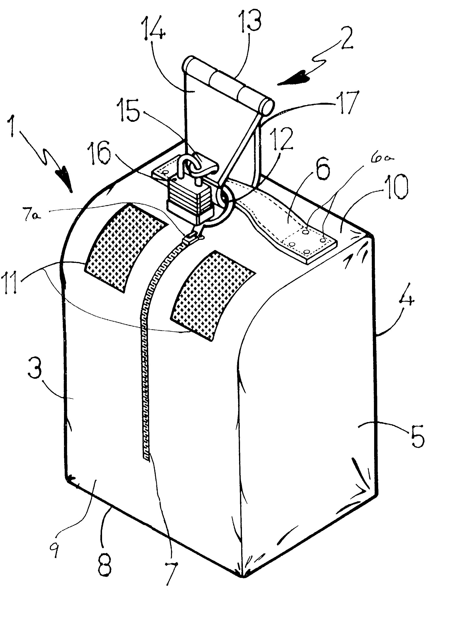
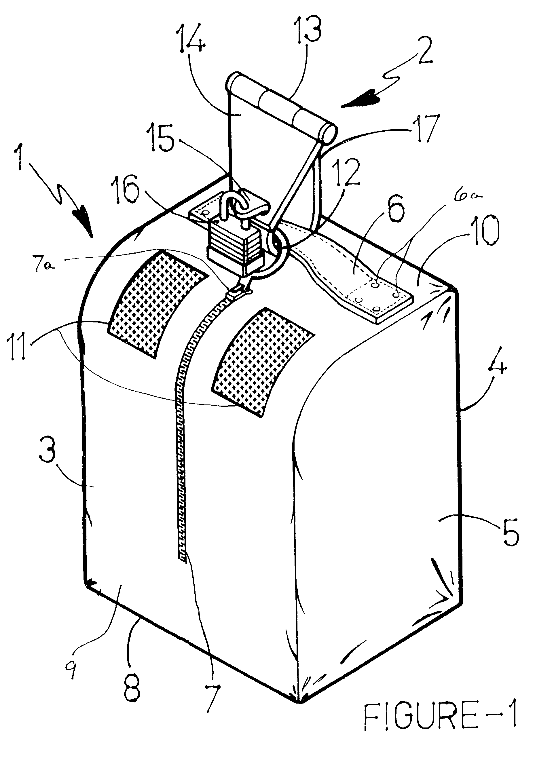
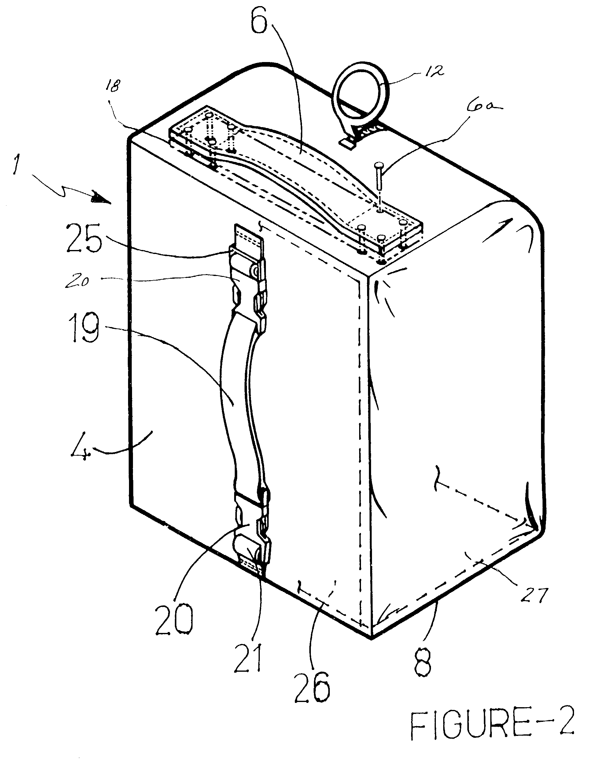
[0014]The locker bag apparatus according to the present invention is also preferably configured to be a hanging locker bag apparatus. Specifically, the locker bag apparatus is configured to be hung, for example, by providing a
handle preferably in an upper portion of the locker bag apparatus. The portable hanging locker bag apparatus according to the present invention is preferably provided with at least one interior compartment and at least one zipper or other type of sliding resealable closure to provide access to at least one compartment within the portable hanging locker bag apparatus. Preferably, the zipper is a
heavy duty plastic or
metal teeth type zipper having some measure of strength to prevent intentional breaking or otherwise tampering thereof. In a preferred embodiment, the zipper is configured to be locked closed. In a more preferred embodiment, the zipper is provided with a sliding tab having a ring portion, which together with the
handle of the portable hanging locker bag apparatus is locked closed when placed on a locking hook according to the present invention.
[0015]The zipper is preferably provided in a
front panel of the locker bag and oriented in a substantially vertical direction. Further, preferably the zipper is arranged so that the zipper is open when the sliding tab is located at a lower position and is closed when the sliding tab is pulled to an upper position so that a ring of the sliding tab is positioned adjacent to the
handle of the locker bag apparatus according to the present invention. In one embodiment, the zipper begins at the lowest position of the
front panel of the locker bag apparatus, however, more preferably, the zipper begins at a position above a lower edge of the
front panel so that the entire front panel cannot be opened. In this manner, shoes and other personal belongings located in a lower portion of the portable bag apparatus cannot easily fall out of the locker bag apparatus when fully opened by the zipper due to the lower front panel of the locker bag apparatus remaining fixed or closed and acting as a tray type support.
[0018]The locker bag apparatus is preferably made of pliable or flexible or “soft” material, preferably a high strength fabric or
textile material such as nylon,
polyester and other suitable polymers or blends of materials. However, leather or synthetic leather can be suitable in some applications such as one or more panels or components of the locker bag apparatus according to the present invention. The use of high strength fabric material results in a light weight, strong, durable and somewhat theft proof locker bag apparatus. The locker bag apparatus can be reinforced with internal
layers or sheets of material (e.g. plastic sheeting or
metal layers or sheeting). The reinforcing
layers can be located internal of the locker bag apparatus or located within layers of materials during the manufacture of the material and / or construction or
assembly of the locker bag apparatus. For example, a substantially rigid plastic panel is inserted within the bottom of the locker bag apparatus to provide rigidity and reinforcement to the bottom fabric panel of the locker bag apparatus. Alternatively, a plastic tray is placed within the bottom of the fabric locker bag apparatus to reinforce the lower portion of the locker bag apparatus to prevent collapse thereof, and to provide a more secure support for shoes and other items to be stacked up within the locker bag apparatus. Preferably, the locker bag apparatus is provided with a vertical reinforcement structure such as a substantially rigid panel, rod, sheet or cage to maintain the height dimension of a flexible or soft locker bag apparatus.
[0021]The locking wall hook according to the present invention is configured to be attached or mounted on a wall in the athletic facility. For example, the wall can be made of
gypsum board, and the locking hook according to the present invention can be anchored to the wall utilizing conventional wall hook anchors. Alternatively, the wall can be plaster or a masonry wall (e.g.
cement block wall), and appropriate plaster or
cement block wall anchors are utilized for mounting the locking wall hook according to the present invention to the plaster or
cement block wall. The locking wall hook according to the present invention can be configured to utilize a combination lock (e.g. key type or combination type), or alternatively, the locking wall hook is provided with an integral lock (e.g. key type or combination type or electronic keypad type). It is desirable that the locking wall hook according to the present invention is configured so that the locker bag apparatus can be hung on the locking wall hook and suspended prior to locking the locking wall hook. Thus, a person would not need to hold up the locker bag apparatus with one hand while attempting to lock the locking hook with the other hand. In this manner, a user will have both
hands free for the purpose of closing and locking the wall hook after the locker bag apparatus has been hung from the locking wall hook to provide convenience and make it easier to lock the locking wall hook.
[0022]The present invention is also directed to a
system utilizing a plurality of locker bag apparatus according to the present invention in combination with a plurality of locking hooks, preferably locking hooks according to the present invention. For example, a plurality of locking wall hooks according to the present invention can be mounted on a wall in a row and / or column or matrix (i.e. both rows and columns). In this manner, the number and density of the locker bag apparatus to be stowed on a particular wall area can be greatly increased reducing the
capital cost in designing and constructing the athletic facility, or having an existing
recreation facility retrofitted to utilize the locker bag apparatus according to the present invention. Preferably, the locking wall hooks are equally spaced in rows and / or columns with sufficient spacing to allow easy and convenient hanging of the locker bag apparatus, or use thereof especially in a crowded
recreational facility.


